
3V Battery To 5V Dc/Dc Converter

The described circuit serves as a DC-DC boost converter, facilitating the conversion of a low input voltage from a battery source to a higher output voltage suitable for logic applications. The circuit is designed to efficiently convert 3 V to a stable 5 V output while delivering a current of up to 40 mA, achieving an efficiency of approximately 85%.
The core functionality is based on a switching regulator topology, where the integrated circuit (IC) plays a pivotal role in controlling the switching of an external inductor. When the IC's pin 6 is driven low, the output voltage is determined by the input battery voltage minus the forward voltage drop across diode D1. This drop is a critical factor to consider, as it directly impacts the output voltage level.
Additionally, the circuit incorporates an optional feature that utilizes capacitor C1, along with resistors R3 and R4, to modulate the oscillator frequency in response to decreasing battery voltage levels. When the battery voltage drops to 2.0 V, the oscillator frequency is reduced. This adjustment is crucial, as it allows the circuit to maintain its output power capability in the face of diminishing input voltage. By lowering the frequency, the peak inductor current increases, which compensates for the reduced input voltage, ensuring that the output remains stable and meets the required specifications for 5-V logic supply.
In summary, this circuit design effectively addresses the challenge of powering 5-V logic devices from lower voltage battery sources, while also incorporating features that enhance performance under varying input conditions. The combination of efficient voltage conversion, output stability, and adaptive frequency response makes this circuit a robust solution for portable electronic applications. A common power-supply requirement involves converting a 2.4- or 3-V battery voltage to a 5-V logic suppl y. This circuit converts 3 V to 5 V at 40 mA with 85% efficiency. When Ic (pin 6) is driven low, the output voltage will be the battery voltage minus the drop across diode Dl. The optional circuitry that uses CI, R3, and R4 lowers the oscillator frequency when the battery voltage falls to 2.0 V.
This lower frequency maintains the output-power capability of the circuit by increasing the peak inductor current, which compensates for the reduced battery voltage.
Related Circuits
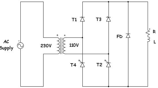
Controlled rectifiers are line-commutated AC to DC power converters that convert a fixed voltage and fixed frequency AC power supply into a variable DC output voltage. The input supply provided to a controlled rectifier is an AC supply with...
This circuit utilizes the NE555 integrated circuit configured as a stable multivibrator. It generates a rectangular wave frequency of approximately 100 Hz, outputting from pin 3 through capacitors C3 and C4, preceding the rectifier power section. The circuit employs...
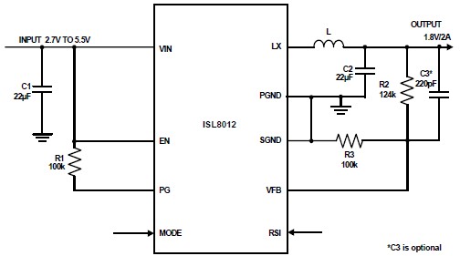
The ISL8012 is a high-efficiency, monolithic, synchronous step-down DC-DC converter that can be designed into a simple electronic project. It supports a maximum continuous output current of up to 2A from an input supply range of 2.7V to 5.5V....
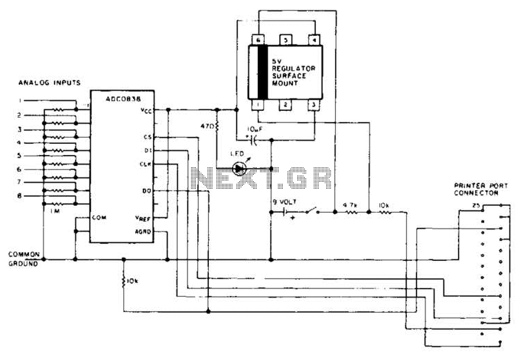
An A/D converter by National Semiconductor (ADC0838) converts 0 to 5 V analog inputs into a digital data format. A 9 V battery is utilized. The converter connects to the pointer port connector through a 25-pin connector. The ADC0838 is...
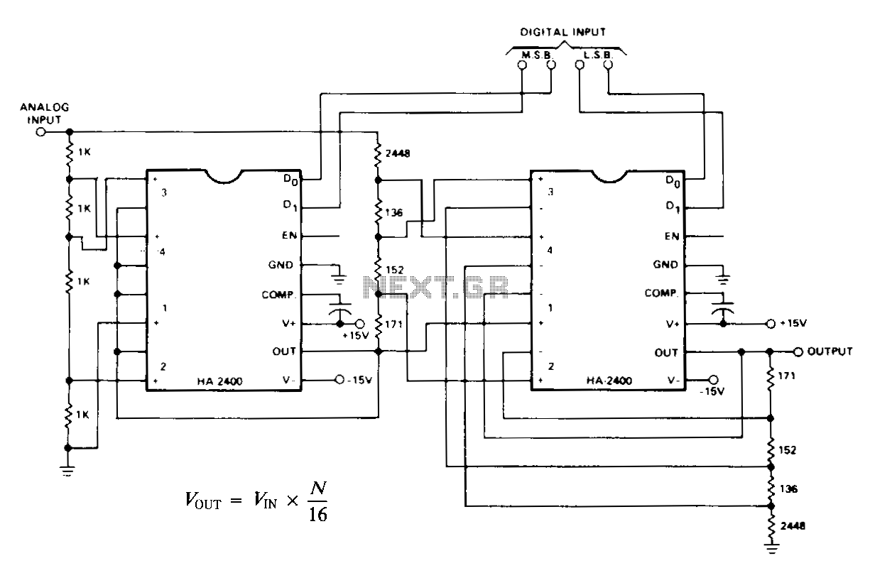
N represents a binary number ranging from 0 to 15, generated by the digital input. When the analog input is set to a fixed DC reference, the circuit functions as a standard 4-bit digital-to-analog converter (DAC), producing an output...
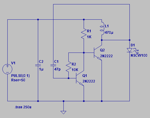
Four observations regarding the Joule Thief AA battery LED circuit. The schematic of the LED circuit illustrates the power source (V1), which symbolizes a depleted battery with only 1 volt remaining and an internal resistance. The Joule Thief circuit is...