This circuit utilizes the NE555 integrated circuit configured as a stable multivibrator. It generates a rectangular wave frequency of approximately 100 Hz, outputting from pin 3 through capacitors C3 and C4, preceding the rectifier power section. The circuit employs both positive and negative DC voltages in series. The positive power supply operates with rectifiers D1 and D2, allowing positive signals to pass through D2 to the output. The signal is then filtered by C5 to smooth the voltage. Conversely, if a negative signal is present, it passes through D1 to ground. The negative power is managed by rectifiers D3 and D4, with negative signals routed through D3 and filtered by C6 to achieve a smooth output. When a positive signal is present, D4 connects to ground. The input power supply to IC1 results in an output frequency of 1 kHz from pin 3, with Q1 and Q2 functioning in a push-pull configuration. Upon receiving a positive output signal, Q1 and Q2 execute a deletion function, necessitating the use of capacitors C2 and C3 for half-wave rectification. The circuit is designed with IC1, R1, R2, and C1 to create an astable multivibrator, producing a square wave output with a frequency of 2.3 kHz from pin 3 of IC1. Capacitor C3 and diode D1 form a clamp circuit, converting positive pulse signals into negative pulse signals. Diodes D2 and C3 work to convert these negative pulse signals into direct current (DC) electrical signals. This configuration allows for the generation of a negative DC output voltage. The circuit serves as a power supply, capable of modifying a 6-volt input to produce a 12-volt DC output. The operational principle involves Q1, Q2, R1, R2, R3, R4, R5, D1, C1, and C2 forming the astable multivibrator model, resulting in a square wave output with variable frequencies. Resistor R6 limits the current flowing to the base of Q3 and the collector of Q4. When current flows into the base of Q3, it biases Q3, while Q4 remains unbiassed due to the lack of current at its base. When Q3 is biased, current flows through inductor L1, causing diode D2 to conduct and Zener diode ZD1 to regulate the output voltage, which increases to 12 volts. Resistor R7 limits the current to the base of Q4, allowing Q4 to turn on and stop biasing Q3, resulting in a zero-volt output. When a positive pulse signal is applied through R6, Q3 is biased again, allowing the circuit to operate cyclically and maintain a consistent 12-volt output. Capacitor C3 filters the current smoothly before it is utilized. This circuit also includes a 3-volt car adapter utilizing the LT1074CT switching regulator IC. The schematic illustrates the LT1074CT functioning as a buck converter, converting a +12-volt car battery voltage down to +3 volts for powering personal hi-fi systems and handheld games, particularly for children during long car journeys. At under ten years of age, children are typically indifferent to any noise generated by the switching circuit. The circuit operates with an AC power supply of 220 volts, where transformer T1 reduces the voltage to approximately 9 volts AC. This AC voltage is converted to DC using rectifiers D1 through D4, forming a bridge rectifier circuit. Capacitor C1 further filters the output, providing a smoothed DC voltage of approximately 12 volts. Diode D5 prevents AC voltage from reaching the output, ensuring that the current flowing into pin 1 of IC1 is regulated to 5 volts at the output of IC1 for testing purposes.This circuit is used IC number NE555 set up to stable multi vibrator. It produces a frequency rectangular patch of about 100 Hz. Out to pin 3 through C3 and C4. Before the rectifier power section. Both positive and negative DC 2 series. Positive power supply will work with the rectifier D1 and D2. When a positive signal to be via D2 to the output. And filtered from C5 to filter the pressure to smooth again. But if there is negative signal to the D1 and down through the ground. The negative power of the D3 and D4 the rectifier. When a negative signal to the output signal to be via D3. And will be filtered from C6 to smooth again. When a positive signal to be via a D4 to ground. When the power supply input to IC1 is the output pin 3 at a frequency of 1 kHz. The frequency is Q1 and Q2, which will continue to use push pool work interchangeably. If this is the positive output signal Q1 Q2 will run the delete function this reason, C2 and C3 capacitors are half-wave alternating. Work of the circuit is IC1, R1, R2 and C1. The range of the A Stable Multi Vibrator, and the output is a square wave. It is a positive signal pulse frequency of 2. 3 kHz output pin 3 of IC1. And C3 and D1 connected to circuit CLAMP. That it serves to signal a positive pulse to pulse signal negative. The D2 and C3 act negative pulse signal is converted direct current (DCV) electrical signals. The negative power. Thus the output voltage to a negative DC electrical. This circuit is power supply circuit, again the circuit that have the merit is if we want dc voltage 12V but, we have 6 volt only the circuit can modify DC voltage 6 Volt be 12VDC get.
The principle works of the circuit is Q1, Q2, R1, R2, R3, R4, R5, D1, C1 and C2 build the circuit is model astable multi vibrator give output be Square Wave. Which be positive pulse signal at have many frequency. And have R6 perform be limit current already flow come to reach at a pin B of Q3 and a pin C of Q4 in this condition current at flow come in pin way B of Q3 make Q3 bias.
But Q4 still not bias. Because of still have no current bias at a pin B. When Q3 bias make have current flow through L1, D2 change ZD1 cause drop voltage at ZD1. Which be output voltage and voltage this increase continually poverty voltage that equal to 12 the volt. By have R7 be limit current already change come in the way pin B of Q4 make Q4 work be make Q3 stop bias.
Then make output voltage be 0 volt, but when positive pulse signal that made come to then change come to at R6 then make Q3 bias again. And work character as before but there are many speeds then can make output that appear can come out 12 volt all the time by have C3 perform in something current filter smoothly before increasingly lead output voltage go to be usable.
This 3 volts Car Adapter circuit is based on a standard LT1074CT switching regulator IC. The schematic shows the LT1074CT used as a positive step-down or buck` converter. The switcher` is used to convert a +12-volt car battery voltage down to +3 volts for use with the personal hi-fi`s and handheld games for the author`s two boisterous children on long car journeys. Note at under ten years of age, children will rarely be hi-fi aficionado`s and are generally not concerned with any noise generated by the switcher circuit.
[. ] Work cycle is entering AC Current power supply 220Volt the transformer T1 will convert AC to lower left 9V will be switched from AC power into DC with D1-D4 connected to circuit Rex Comment fire Bridge Terminal. (Bridge-Regtifier) will be Current Filter to smooth further the capacitor C1, which at this point can be used as Vout by`ll volt approximately 12Volt the output level one will be diode D5 acts to prevent AC voltage.
through the connection of the output level will be a DC current flowing into pin 1 of IC1 by IC1 acts as the regulated voltage to 5 volts out in three legs of IC1, the output level. To test the circuit or circu 🔗 External reference
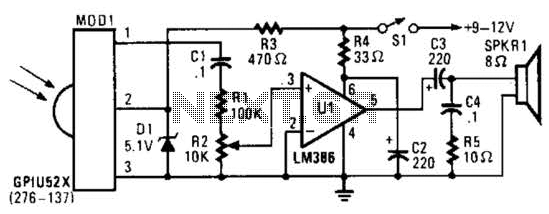
This circuit utilizes an infrared pulse-to-audio converter to assist in troubleshooting infrared remote controls, making it an effective tool for detecting infrared light sources. It employs a photo cell module (Radio Shack P/N 276-137) to detect IR radiation and...
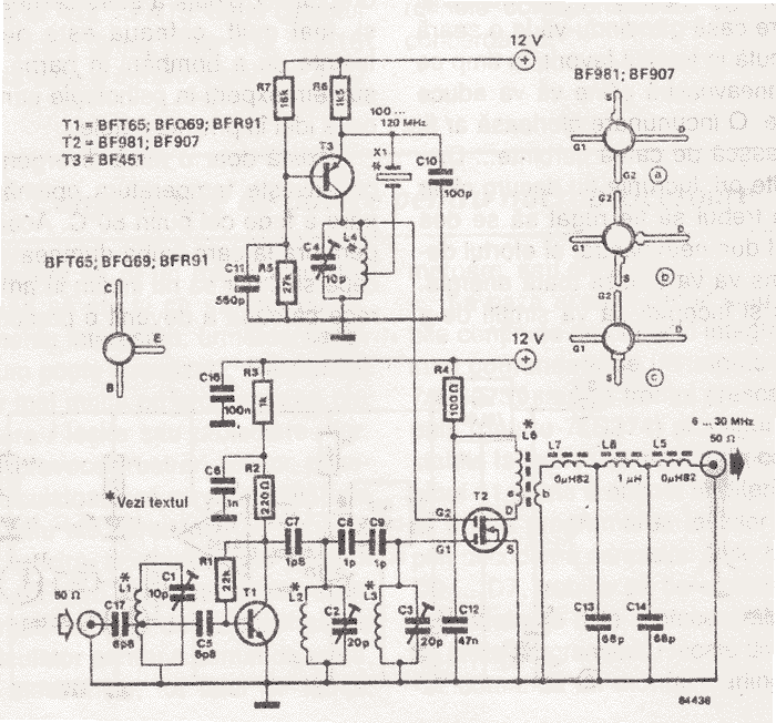
There are many individuals interested in listening to frequencies within the VHF range of 108 to 132 MHz. This VHF AM converter is designed to convert signals from a frequency band of 106 to 150 MHz, allowing users to...
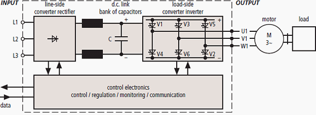
Frequency converters are safeguarded against surges using surge protective devices, for which the maximum continuous operating voltage (Uc) must be considered.
Frequency converters are critical components in various electronic applications, converting input frequencies to desired output frequencies. To ensure their...
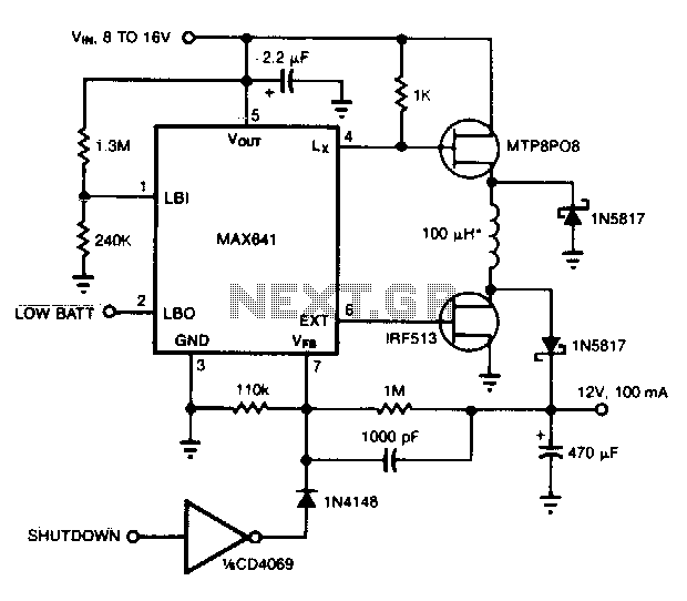
This converter can accommodate wide input voltage swings, such as the 8 to 15 V range typical of a 12 V sealed lead-acid battery. The low battery output indicates when the input voltage drops below 8 V. Pulling the...
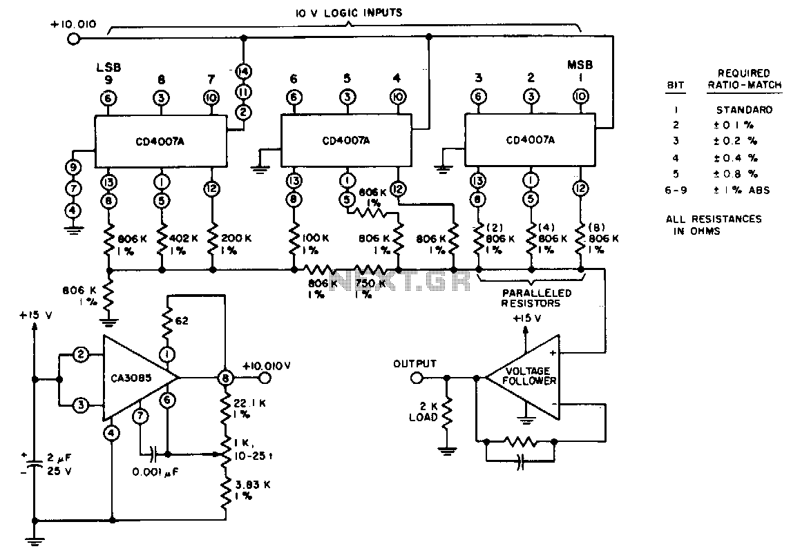
Three CD4007 A integrated circuit packages perform the switching function using a 10-V logic level. A single 15-V supply provides a positive bus for the follower amplifier and powers the CA3085 voltage regulator. The scale adjustment function is facilitated...
Individuals who frequently utilize battery-operated devices or require a negative voltage from a single positive source will find the following converter beneficial. This circuit can convert a 9 V positive battery voltage to a negative voltage using the well-known...
We use cookies to enhance your experience, analyze traffic, and serve personalized ads.
By clicking "Accept", you agree to our use of cookies.
Learn more