
3V to 24V Variable Power Supply

This circuit provides a versatile power supply solution suitable for various electronic applications. The adjustable output voltage allows for flexibility in powering different devices, while the current limiting feature ensures protection against overload conditions. The choice of transistors, 2N3055 and 2N3053, is critical for handling the output current efficiently, and the use of adequate heat sinks is necessary to dissipate heat generated during operation, particularly when operating at higher currents.
The operational amplifier plays a vital role in maintaining voltage regulation. The 1558 or 1458 op-amp is configured in a feedback loop that monitors the output voltage and adjusts the transistor's base drive accordingly to maintain a stable output. The inclusion of a current sense resistor allows for monitoring the output current, and its value can be adjusted to set the desired current limit.
The power transformer is selected based on the required output voltage and current ratings. The center-tapped configuration enables multiple output voltages, providing versatility in application. The transformer must have a voltage rating that accommodates the output needs while maintaining a sufficient margin above the maximum output to ensure proper regulation.
In summary, this power supply circuit combines adjustable voltage output, current limiting, and effective thermal management, making it suitable for a range of electronic projects. Proper component selection and configuration are essential for optimal performance and reliability.This 3V to 24 volt variable-regulated power supply can be adjusted from 3 to 25 volts and is current limited to 2 amps as shown, but may be increased to 3 amps or more by selecting a smaller current sense resistor (0. 3 ohm). The 2N3055 and 2N3053 transistors should be mounted on suitable heat sinks and the current sense resistor should be rated at
3 watts or more. Voltage regulation is controlled by 1/2 of a 1558 or 1458 op-amp. The 1458 may be substituted in the circuit below, but it is recommended the supply voltage to pin 8 be limited to 30 VDC, which can be accomplished by adding a 6. 2 volt zener or 5. 1 K resistor in series with pin 8. The maximum DC supply voltage for the 1458 and 1558 is 36 and 44 respectively. The power transformer should be capable of the desired current while maintaining an input voltage at least 4 volts higher than the desired output, but not exceeding the maximum supply voltage of the op-amp under minimal load conditions.
The power transformer shown is a center tapped 25. 2 volt AC / 2 amp unit that will provide regulated outputs of 24 volts at 0. 7 amps, 15 volts at 2 amps, or 6 volts at 3 amps. The 3 amp output is obtained using the center tap of the transformer with the switch in the 18 volt position. All components should be available at Radio Shack with the exception of the 1558 op-amp. 🔗 External reference
Related Circuits
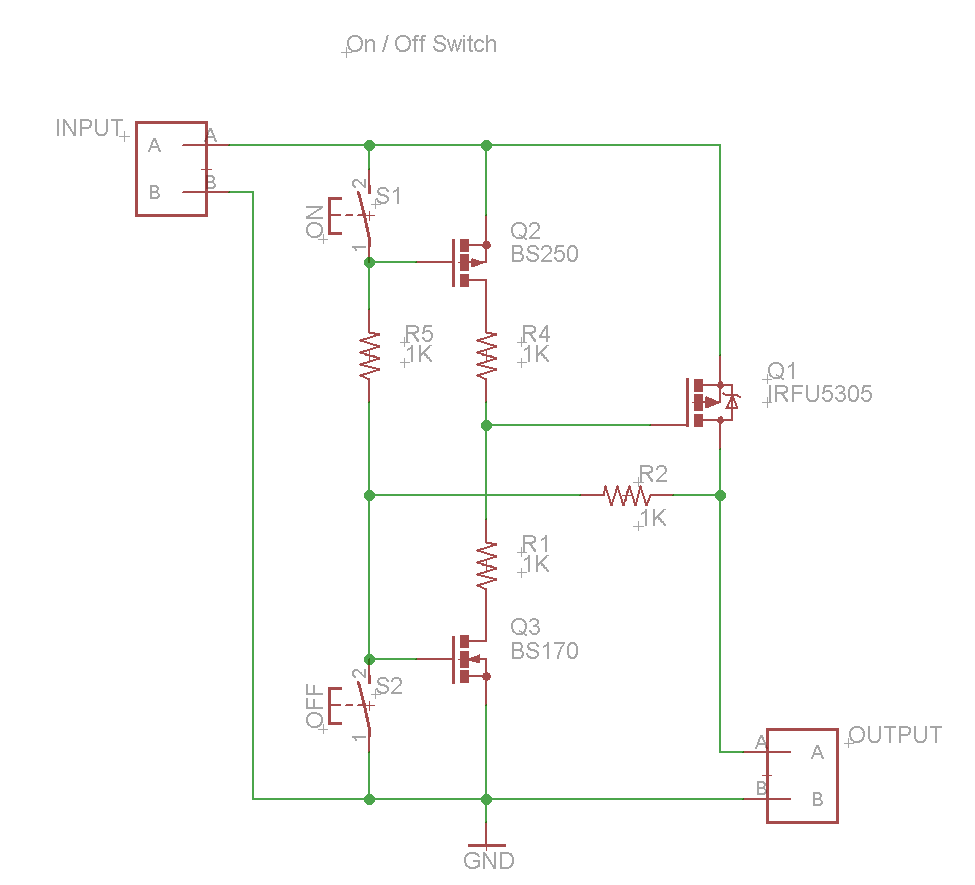
A power button configuration consisting of two buttons, one for turning on and another for turning off. This system is required to switch a voltage of approximately 15 V and a current of up to 10 A for a...
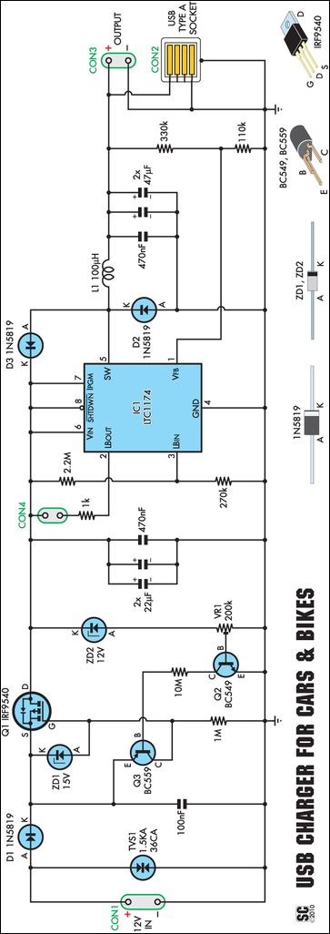
An efficient USB charger designed to operate from a 12V car battery, achieving up to 89% efficiency and capable of charging USB devices at currents up to 525mA. It does not drain the battery if left permanently connected, provided...
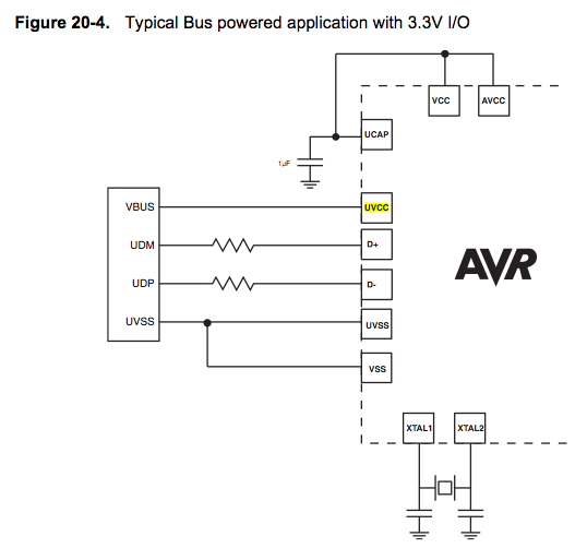
Since the microcontroller unit (MCU) is powered through USB, the common zero voltage should align with the supply voltage and thus be connected to the 0V (UVSS) line. In electronic circuit design, it is essential to ensure that the ground...
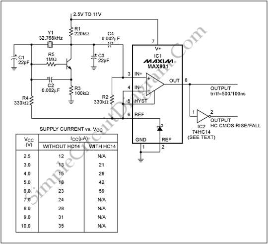
To generate a system clock or auxiliary sleep clock in microcontrollers (µCs) and low-power instruments, a 32 kHz oscillator is commonly utilized. This oscillator typically employs a CMOS inverter. A 32 kHz oscillator is essential for various timing functions in...
This circuit utilizes a 74HC14 hex Schmitt trigger inverter as a square wave oscillator to drive a small signal transistor configured in a class C amplifier setup. The frequency of the oscillator can be either fixed using a crystal...
This is an audio power amplifier that delivers 40 W at 8 ohms in Class A operation. The power transistors are continuously active, enabling a substantial current to flow. The audio power amplifier described operates in Class A mode, which...