
4 Band Double Tuned Preselector

This project involves a versatile antenna interface designed to accommodate both longwire and loop antennas, effectively enhancing reception capabilities across medium wave (MW) and shortwave (SW) frequencies up to 30 MHz. The circuit is engineered to optimize signal capture and minimize noise interference, making it suitable for various applications in amateur radio and shortwave listening.
The antenna input stage is designed to accept signals from either a longwire or a loop antenna, allowing users to select the most suitable option based on their environment and reception needs. The input impedance is typically matched to 50 ohms or 75 ohms, depending on the specific design requirements, ensuring efficient power transfer from the antenna to the subsequent amplification stages.
The circuit may include a low-noise amplifier (LNA) to boost weak signals received from the antenna, thereby improving overall reception quality. The LNA is often followed by a band-pass filter that selectively allows frequencies within the MW and SW range while attenuating unwanted signals outside this band. This filtering process is crucial for maintaining clarity and reducing interference from nearby electronic devices.
Additionally, the design may incorporate a tuning mechanism, such as a variable capacitor or a digital tuning circuit, to allow users to adjust the resonance of the antenna system. This tuning capability is essential for optimizing reception for specific frequencies within the 30 MHz range.
Power supply requirements for the circuit can vary, but typically a low-voltage DC source is sufficient to power the LNA and any active components. Proper grounding and shielding techniques should be employed to further minimize noise and enhance signal integrity.
Overall, this antenna interface project exemplifies a practical approach to enhancing radio frequency reception, making it a valuable addition for enthusiasts looking to improve their listening experience across a wide range of frequencies.Once again, this is a project designed by David Sayles. The input can be from a longwire or a loop antenna. The unit covers MW and Sw to 30MHz. Click here for a picture of David`s MW loop. Click here to view a finished picture of this project. 🔗 External reference
Related Circuits
The circuit design utilizes a VHF amplifier configured to operate within the frequency range of 88 to 108 MHz, specifically for Band 2 radio applications. The VHF amplifier circuit is designed to enhance weak radio frequency signals in the specified...
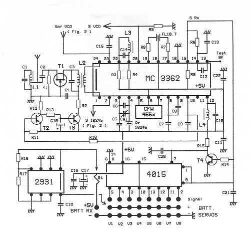
This receptor is born of our annoyance against the irritating problem of Quartz: With the RX21, completed research of cut crystal for your personal rating, you have with him, access to ALL band frequencies, in steps of 5 kHz!...
The circuit was designed to create ten different frequency bands that can be processed by a single graphic equalizer to produce and maintain a predetermined frequency response. The described circuit is a graphic equalizer that utilizes a multi-band approach to...
This application note presents alternate RF matching networks for the MAX2653 SiGe LNA, tuned for the GPS band (1575 MHz center frequency). Performance metrics (supply current, forward gain, noise figure, IIP3, reverse isolation, and input/output return loss) for both...
D1, D2, C1, and C2 double the AC input voltage, charging capacitor C3 through resistor R1 to approximately 320 volts. Resistor R1 isolates the voltage doubler from the discharge capacitor C3, ensuring that capacitors C1 and C2 do not...
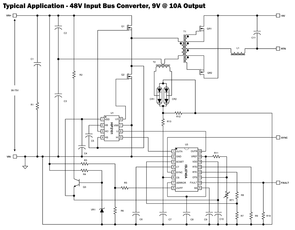
The ISL6740A is an enhanced PWM controller that incorporates built-in voltage feed forward functionality. It is pin and feature compatible with the ISL6740 double-ended pulse width modulation (PWM) voltage-mode controller, facilitating straightforward drop-in replacement in existing designs. Voltage feed...