
Voltage-Doubler Circuit

The circuit operates by utilizing a voltage doubling technique through diodes D1 and D2, coupled with capacitors C1 and C2, which effectively increases the AC line voltage. The output voltage across capacitor C3 is regulated to approximately 320 volts, which is essential for the operation of the flashtube. The isolation provided by resistor R1 is critical, as it prevents the voltage doubler capacitors from discharging during the flashtube operation, thus maintaining circuit integrity.
The relaxation oscillator, formed by the combination of R2, D3, and the associated components (R3, R4, R5, R6, and C4), operates at a predetermined frequency, allowing for controlled triggering of the SCR. The SCR is responsible for managing the discharge of capacitor C5, which energizes the trigger coil. The repetitive discharging of C5 generates the necessary pulse to activate the flashtube, producing a flash of light.
Resistors R7 and R8 serve a dual purpose: they not only limit the voltage across the SCR, ensuring it operates within safe parameters, but they also help to stabilize the circuit against voltage spikes that may occur during operation. The calculated energy output of 5.12 joules indicates the potential intensity of the flash produced, emphasizing the need for caution due to the presence of hazardous voltages. Overall, the circuit is designed for efficient energy transfer while maintaining safety and reliability in operation.D1, D2, C1, and C2 double the AC line in, charging C3 through R1 to approximately 320 volts. R1 isolates the voltage doubler from the discharge capacitor C3 so that C1 and C2 do not participate in the flashtube discharge path. R2 and D3 form a 16-volt supply for a relaxation ocillator from parts R3, R4, R5, R6, C4, and the PUT.
This gates the SCR at approximately 60-70 times each minute, which discharges C5 through the primary of the trigger coil, thereby triggering the flashtube. R7 and R8 form a volt age divider to keep the voltage within safe limits for the SCR and C5. The flash energy produces 320x320x. 0001x. 5=5. 12joules. CAUTION: Hazardous voltage exists within this circuit that can deliver a substatial shock, as is the case with most circuits that are powered off of a 110-volt line.
🔗 External reference
Related Circuits
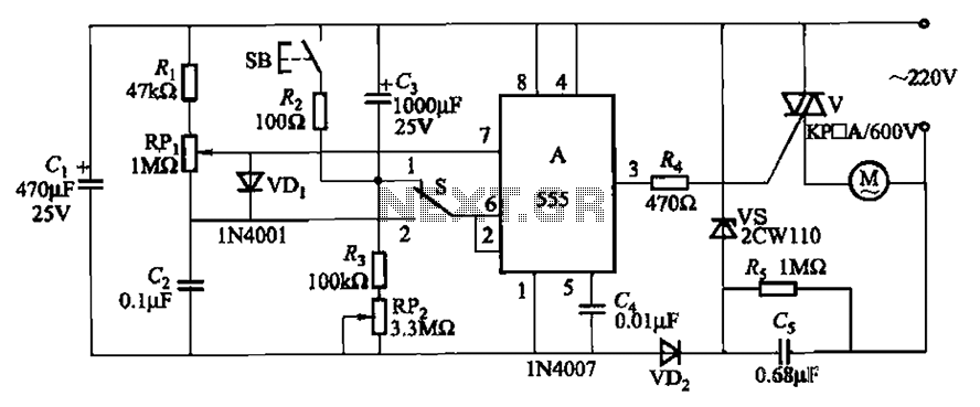
The circuit illustrated in Figure 3-12 incorporates variable speed and timing control functions. When switch S is set to position 1 and button SB is pressed, the motor initiates operation. After a predetermined delay, the motor automatically shuts down....
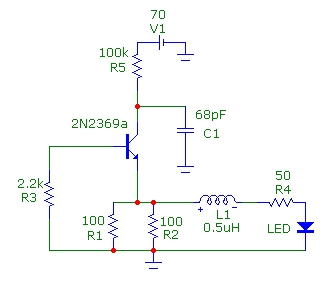
This article presents basic circuits for pulsing infrared LEDs and low-power visible semiconductor lasers utilizing inexpensive and readily available components. Numerous interesting and practical applications are referenced, alongside several online resources. The focus of the article is on the...
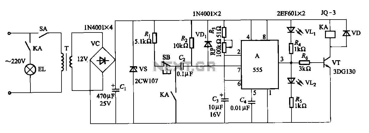
The second circuit for darkroom time exposure utilizes a 555 timer integrated circuit (IC A) for timing functions. A relay controlled by the circuit regulates the exposure light source. The exposure time can be adjusted using potentiometer RP, allowing...

Using two LT1228 transconductance amplifiers in front of a current feedback amplifier creates a video fader. The ratio of the set currents into pin 5 determines the ratio of the inputs at the output. The proposed circuit utilizes two LT1228...

The circuit features a serial coded modulated control signal that amplifies and transmits high-voltage isolation. It utilizes a 556 timer-based circuit along with resistors R1, R2, capacitors C1, and R3, R4, C2 to form two astable multivibrators. The circuit...
This circuit is designed to dim lights with a maximum capacity of approximately 350 watts. It employs a standard TRIAC circuit configuration, which has been observed to generate minimal heat during operation. It is important to note that this...