
4 Direct drive LCD display circuit diagram

The LCD (Liquid Crystal Display) system operates through a series of interconnected components that manage the visual output. Each segment of the LCD is equipped with its own counter, latch, decoder, and driver, allowing for precise control over the displayed information. The counter is responsible for counting the incoming signals, while the latch holds the current state of the display until it is updated. The decoder translates the binary input data into signals that can be understood by the driver, which ultimately activates the individual pixels of the display.
Feedback from the pumping signal to the motherboard is crucial for maintaining synchronization between the display and the control circuitry. This feedback mechanism ensures that when the display section is disconnected, the signals from the motherboard and the display segment are in phase and have the same amplitude. As a result, no voltage is detected across the terminals of the display, indicating that the system is in a safe state and preventing potential damage.
When the display segment is triggered, the pumping signal is energized, allowing the individual pixels to change their state and produce the desired visual output. This activation process requires careful timing and control to ensure that the display functions correctly and responds accurately to input signals. The design of the LCD system emphasizes reliability and precision, making it suitable for a wide range of applications in consumer electronics, industrial displays, and other fields where visual information is critical.Each part of LCD has individual counter, latch, decoder and driver. Pumping signal feeds back to the motherboard of LCD. When the display section is disconnected, the phase and amplitude of the motherboard and display segment drive signal are the same. It shows no voltage on the 2 ends of display. When the display segment is triggered, its pumping signal p.. 🔗 External reference
Related Circuits

The clock pulses from the 555 astable circuit are sent into the 4017 decade counter. Each output becomes high in turn as the clock pulses are received. Appropriate outputs are combined with diodes to supply the amber and green...
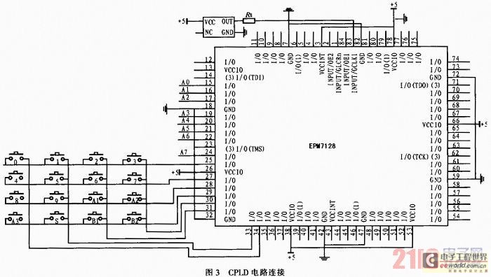
The system utilizes a modular design featuring the AT89S52 microcontroller and CPLD as the central processing unit (CPU) for overall system coordination. Initially, it establishes a cycle of systematic pulse signals through a 4G-4 key set module, allowing for...
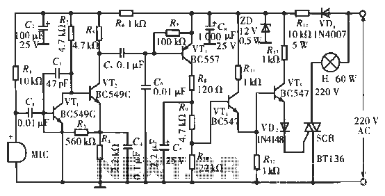
The circuit utilizes condenser microphones to detect sound and convert it into signal variations. This signal is then processed through directly coupled transistors VT1 and VT2, which form an amplification stage before being fed into a switching circuit. The...
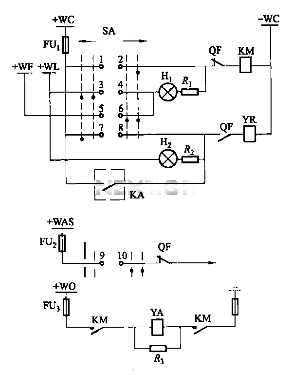
Factories and enterprises operating at voltages of 10 kV and below commonly utilize the CD10 (formerly CD2) type electromagnetic actuator as a circuit breaker. This mechanism features a mechanical anti-jump device. The control signal circuit for the CD10 actuator...
The standard Class AB audio power amplifier allows for direct coupling of the amplifier's output to speakers. This is beneficial as it eliminates capacitors or transformers that could compromise sound quality. The speakers are connected directly to the amplifying...
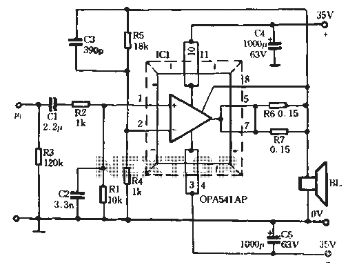
The Burr-Brown OPA541 chip is a power amplifier capable of operating with a maximum power supply voltage of 40V, delivering a continuous output current of up to 5A. The output current can be adjusted using an external resistor to...