
Breaker control signal circuit of the electromagnetic actuator

The CD10 electromagnetic actuator is integral to the operation of circuit breakers in low-voltage applications, particularly in industrial settings. The actuator's design incorporates a mechanical anti-jump device, ensuring reliable operation and enhanced safety. The control signal circuit, as depicted in Figure 6-70, outlines the various connections and functionalities essential for effective circuit management.
The circuit includes multiple components that facilitate the operation of the actuator. The small bus control (wc) is crucial for managing the flow of signals to the actuator, while the light indicator (WL) provides visual feedback regarding the status of the small bus. The flash signal bus (WF) is used for alerting operators of specific conditions, and the accident sound bus (WAS) serves as an auditory warning system in case of faults or emergencies.
The closing gate control (w0) is responsible for the physical actuation involved in closing the circuit, while the switch control (SA) allows for manual intervention when necessary. The circuit breaker (KM) acts as a safety device, ensuring that the electrical circuit is interrupted in case of overloads or faults. The trip coil (YR) and electromagnetic closing coil (YA) are critical for the actuation mechanism, providing the necessary electromagnetic force to operate the breaker.
Relay contacts (KA) facilitate the communication between various components of the circuit, allowing for coordinated operation. The green indicator light (Hi) provides a visual cue that the system is functioning correctly, whereas the red LED (H2) indicates a fault or an operational issue. Finally, the discharge resistor (R3) is employed to safely dissipate any residual charge in the circuit, ensuring that the system remains safe for maintenance and operation.
Overall, the CD10 actuator and its associated control circuit play a vital role in the safe and efficient operation of low-voltage electrical systems in industrial environments.Factories and enterprises lOkV and below the circuit breaker commonly used CD10 (formerly CD2) type electromagnetic actuator. This type of mechanism itself has a mechanical ant i-jump device. Adopt breaker control signal circuit CD10 Actuator type shown in Figure 6-70. Figure, wc for the control of small bus; WL for a light indicating a small bus; WF is a small flash signal bus; WAS the accident sound small bus; w0 is closing the gate a small bus; SA controls switch; KM circuit breaker QF closing contacts device; YR to the trip coil; YA electric magnetic closing coil; KA for the export of relay contacts; Hi for the green indicator light; H2 red LED; R3 is a discharge resistor.
Related Circuits
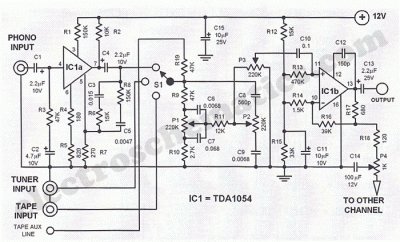
This Hi-Fi stereo preamplifier circuit is constructed using the TDA1054 integrated circuit (IC) from SGS. The TDA1054 is housed in a 16-pin DIL package and incorporates two separate preamplifier circuits. It is characterized by low noise and minimal issues...
The zero-power regulator circuit is simple, reliable, and functional. It is suitable for various electric power adjustment applications, such as series-wound motor power adjustment. The operational principle of the circuit involves several components, including the power circuit, an AC...

This circuit provides protection for telephones, EPABX systems, telephone modems, and similar devices against lightning discharges and line voltage spikes. It incorporates a safety capacitor and gas discharge components. The circuit employs a safety capacitor to filter out high-frequency noise...
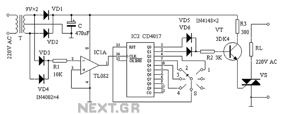
High pressure alarm with high sensitivity. It detects high-voltage electric energy from 10kV at a distance of 2m or from low-voltage mains (AC 220V) at a distance of 0.3m. The alarm device is simple to manufacture, compact, and user-friendly....
Here is a deluxe version of the simple charge rate limiter, using the same idea but with the ability to charge two packs simultaneously from a single wall charger. For circuit description and parts list, see the simple charger...
This infrared (IR) remote extender enhances the range of most basic IR remotes operating at a 40KHz modulation frequency significantly. When in operation, the remote is aimed at the detector on the circuit, and a button is pressed. The...