
4 Transistor Transmitter

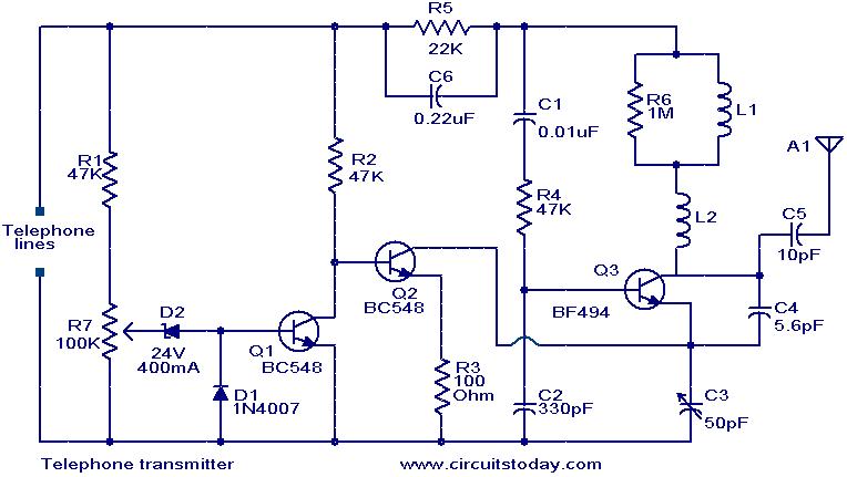
The circuit operates as an FM transmitter, effectively modulating an audio signal onto a high-frequency carrier wave. The Colpitts oscillator serves as the core frequency generation component, where the selection of capacitors and the inductor is crucial for achieving the desired operating frequency. The tank circuit plays a pivotal role in determining the oscillation frequency, and the precise values of the capacitors and inductor must be calculated to ensure the circuit resonates at approximately 100 MHz.
The microphone preamplifier, utilizing the 2N3904 transistors, amplifies the audio signal before it is modulated. The 5 kΩ preset resistor allows for adjustment of the gain, enabling optimization based on the input audio level. This flexibility is essential for adapting to various audio sources.
The modulation process is facilitated by the integration of the 5 pF capacitor and the 10 kΩ resistor, which together with the 1N4002 diode, allow for controlled audio modulation depth. The diode's role is to rectify the signal, ensuring that the modulation does not exceed a certain threshold, thus maintaining signal integrity and preventing distortion.
In the output stage, the Class D amplifier configuration is effective for high-efficiency power amplification. The absence of direct biasing simplifies the design while still allowing the RF signal to drive the output stage effectively. The inclusion of an emitter resistor and a 1 kΩ base resistor is critical for maintaining stability, preventing oscillations that could lead to thermal issues, which is a common concern in high-power RF applications.
Overall, this circuit is a well-designed FM transmitter capable of delivering a robust modulated signal suitable for various applications, including amateur radio and audio broadcasting. Proper attention to component selection and configuration ensures reliable performance and efficient operation.This circuit provides an FM modulated signal with an output power of around 500mW. The input Mic preamp is built around a couple of 2N3904 transistors, audio gain limited by the 5k preset. The oscillator is a colpitts stage, frequency of oscillation governed by the tank circuit made from two 5pF capacitors and the inductor.
( Click here for Colpit t Oscillator Resonant Frequency Equation. ) Frequency is around 100Mhz with values shown. Audio modulation is fed into the tank circuit via the 5p capacitor, the 10k resistor and 1N4002 controlling the amount of modulation. The oscillator output is fed into the 3. 9uH inductor which will have a high impedance at RF frequencies. The output stage operates as a class D amplifier, no direct bias is applied but the RF signal developed across the 3.
9uH inductor is sufficient to drive this stage. The emitter resistor and 1k base resistor prevent instability and thermal runaway in this stage. 🔗 External reference
Related Circuits
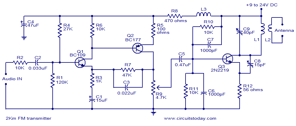
With a matching antenna, the FM transmitter circuit can transmit signals over a range of 2 kilometers. The transistors Q1 and Q2 form a highly sensitive preamplifier stage. The audio signal to be transmitted is coupled to the base...
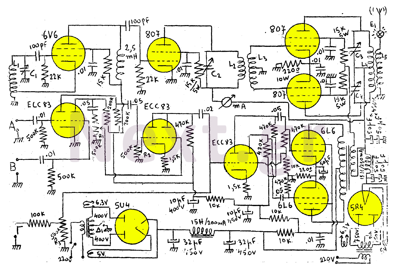
This transmitter consists of a 6V6 oscillator that excites an 807 buffer. The final stage includes two 807 tubes arranged in a Push-Pull configuration. The amplifier is built with three series-connected double-triodes (ECC83) and concludes with two 6L6 tubes...
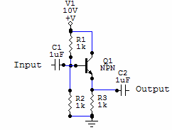
Two examples of the most common types of Voltage followers (buffers). You can find some theory behind them in our amplifier gain and buffer amplifier pages. This first circuit is a very simple one transistor voltage follower. Consists of...
This simple circuit can provide hours of enjoyment as you learn tunes, play duets or just make some really weird sounds by pushing all the buttons at once. You have probably seen this circuit before, it is fairly common....
This is a single-chip FM transmitter circuit utilizing the Maxim semiconductors IC MAX2606. The MAX2606 is a compact, high-performance intermediate frequency voltage-controlled oscillator (VCO) specifically designed for wireless communication applications. It features a monolithic construction that ensures low noise...
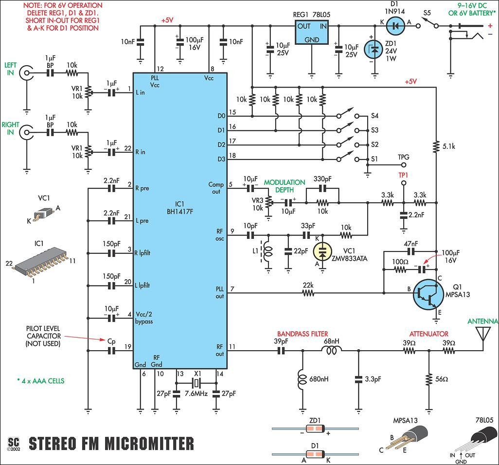
This new stereo FM Micromitter is capable of broadcasting good quality signals over a range of about 20 meters. It is ideal for broadcasting music from a CD player or any other source so that it can be picked...