
4 Watt Amplifier with preamplifier

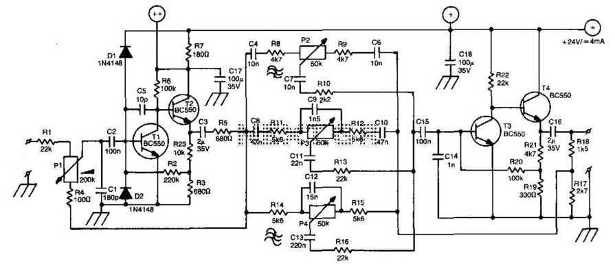
The described amplifier circuit is a compact audio amplification system designed to operate with a supply voltage of 15V, providing a continuous output power of 4.2W into a 4Ω load. The amplifier features a low input signal threshold, requiring only 94mVp-p when used with a preamplifier, or 0.65Vp-p without it, making it suitable for a variety of audio sources.
The circuit components include resistors, capacitors, a transistor, and an integrated circuit (IC) for amplification. The resistors are as follows: R1 (2.2kΩ) acts as a biasing resistor, R2 (330kΩ) helps set the gain of the circuit, R3 (4.7kΩ) is a logarithmic potentiometer that allows for volume control, R4 (330Ω) is used for output loading, R5 (1kΩ) can provide feedback stabilization, and R6 (1.5Ω) is likely a current sensing resistor.
Capacitors play a vital role in this circuit: C1 and C6 (100nF polyester) are used for coupling and decoupling to filter high-frequency noise, while C2 (100μF/25V) serves as a power supply bypass capacitor to smooth voltage fluctuations. C3 and C7 (1mF/25V electrolytic) are used for coupling, and C4 (1000μF/25V electrolytic) provides additional power supply stability. C5 (10μF/25V electrolytic) is another coupling capacitor that can help block DC while allowing AC audio signals to pass.
The transistor Q1 (BC547) is used for signal amplification, while the integrated circuit U1 (TDA2002) is a dedicated audio power amplifier IC that simplifies the design and enhances performance. The output of the amplifier drives a loudspeaker (LS1), which converts the amplified electrical signals back into sound.
The note regarding the loudspeaker's resistance indicates that the output power will vary depending on the speaker's impedance. Lower impedance speakers will draw more current, resulting in higher output power, while higher impedance speakers will reduce the current draw and consequently the output power. This circuit design allows for flexibility in speaker selection, provided the impedance remains within acceptable limits for the TDA2002 IC.A small amplifier with nice characteristics: Tendency of catering: 15V. Force of expense: 4,2Wrms in the 4W. Minimal signal of entry: 94mVp-p with preamplifier, 0,65Vp-p without the preamplifier. Materially: R1=2,2KW R2=330KW R3=4,7KW logarithmic potentiometer R4=330W R5=1KW R6=1,5W C1, C6=100nF polyester C2=100mF/25V ilektrolytjko's C3, C7=1mF/25V electrolytic C4=1000uF/25V electrolytic C5=10uF/25V electrolytic Q1=BC547 U1=TDA2002 LS1=Loudspeaker. Notes: Proportionally the resistance of loudspeaker changes the force that it can give the amplifier
🔗 External reference
Related Circuits
The compact, low-cost condenser microphone audio amplifier described here delivers good-quality audio output of 0.5 watts at a supply voltage of 4.5 volts. It can be utilized as part of intercom systems. This audio amplifier circuit is designed to enhance...
The circuit contributes 3.2 nV/√Hz of voltage noise and 0.45 pA/√Hz of current noise. To minimize noise from other sources, resistor R3 is configured to 100 ohms, resulting in an additional voltage noise of only 1.3 nV/√Hz. Resistors R1,...
The FET operational amplifier (op amp) requires a bipolar voltage at pins 4 and 7, with a common ground to achieve optimum gain. The gain can be calculated by dividing R2 by R1. Zero-set balance can be achieved through...
A line amplifier is a valuable component for matching line signals or increasing their levels. This functionality is essential during recording sessions or in public-address systems. Additionally, multiple line amplifiers can be combined to create a line mixer. The amplifier's...
A Darlington transistor can enhance circuit performance, although it introduces slight complexity. The advantage of using a Darlington configuration lies in its capability to achieve low output impedance. The recommended component is the 2N6426 from Mouser, with alternatives such...
These devices are low-cost, high-speed, dual JFET input operational amplifiers featuring an internally trimmed input offset voltage (utilizing BI-FET II technology). They require low supply current while maintaining a large gain-bandwidth product and fast slew rate. Additionally, well-matched high-voltage...