
MPF102 FET Preamplifier Arduino

The circuit utilizes a Darlington transistor configuration to amplify the input signal from the Arduino, providing a robust control mechanism for motor applications. The 2N6426 is particularly advantageous due to its high current gain, which allows for significant output current with minimal input current, making it ideal for controlling larger loads such as stepper motors. The integration of a phototransistor in the circuit serves as a sensor, which detects the infrared LED's activation and generates a corresponding signal for the motor driver, ensuring precise control.
The choice of resistors in the circuit is critical for maintaining the integrity of the signals. The 220-ohm resistor protects the LED from excessive current, while the 5.6K and 56K resistors help manage the signal levels and protect the Darlington array from potential damage caused by excessive current from the phototransistor. The capacitors included in the design are essential for stability, with the 0.01 µF capacitor effectively filtering out high-frequency noise that could disrupt the operation of the microcontroller and motor driver.
In applications where space is a constraint or where multiple opto-isolators are required, the Vishay 782-ILQ615-3 provides a compact solution. This device simplifies the design by integrating multiple opto-couplers into a single package, reducing the overall component count and PCB space required.
Overall, this circuit design exemplifies a practical application of Darlington transistors and opto-isolators in control systems, ensuring reliable operation while accommodating various design considerations such as component selection and signal integrity.A Darlington would perform even better, but the circuit would be slightly more complicated. (See the schematic at bottom-right. ) Fortunately, the added complexity is inside the part! The reason for the Darlington`s superiority is that it can provide the lowest output impedance. I don`t know how low you need the output impedance to be. For the Darl ington, I strongly recommend the 2N6426 from Mouser. Similar devices are the 2N6427 and MPSA13. Each Darlington transistor is actually an IC with two super beta transistors inside. Either one of these internal devices is a superman. Together, they rule the universe. If you don`t want to try the 2N6426, you could build your own Darlington with two 2N3904 transistors from Radio Shack. Yet two 2N3904s only have a combined gain of 40K. The 2N6426 has a gain of 300K. Either version of the circuit should work, but the 2N6426 has the edge. (All that gain provides extra elbow room in the form of sensitivity. Actually, nobody uses the whole 300K. Think about it: In theory, 1 milliamp on the base gets you 300 amps on the collector. In real life, that much current would crater your PC board!) Here`s the circuit The Arduino digital output pulses an infrared LED that`s in series with a 220-ohm, half-watt resistor.
(One LED for each motor coil. ) The resistor reduces the Arduino current to a safe value for the LED. Be sure to use a half-watt resistor here. The LED could be active-high or active-low. (The drawing below shows both versions of the circuit. ) The 12-volt stepper supply powers the phototransistor. The phototransistor`s emitter is in series with a 5. 6K, quarter-watt resistor. Another resistor, 56K, quarter watt, couples the emitter signal to the Darlington array input. Whenever the LED lights, the phototransistor sends a high pulse to the motor drive chip. A 0. 01 µF capacitor shunts digital noise to ground. A parallel 10 µF capacitor filters low-frequency ripple from the phototransistor supply. The 56K resistor is optional. The purpose of this resistor is to limit current and isolate the phototransistor from the Darlington array. Tweak the value of this resistor as necessary. If your driver requires a little extra voltage, you can remove the 56K resistor. You might prefer to use an opto array instead of discrete optos. Then I suggest the Vishay 782-ILQ615-3 from Mouser. This part comes in a DIP-16 package and includes four opto-couplers. The LEDs in this package will operate adequately with only 10 mA. 🔗 External reference
Related Circuits
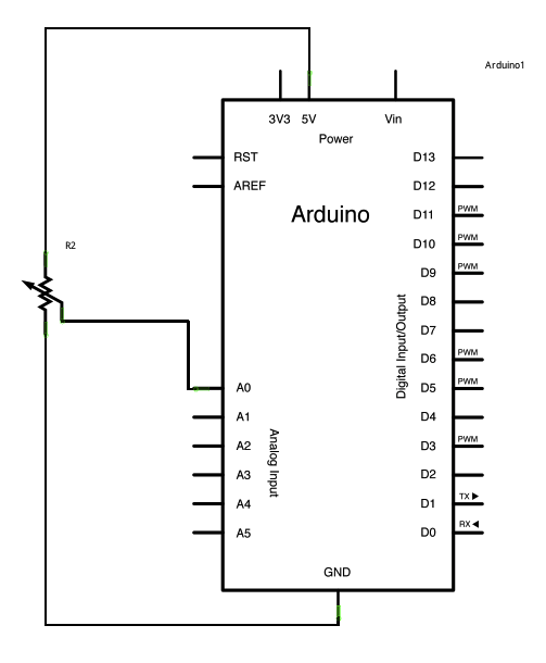
A potentiometer is a simple knob that provides variable resistance, which can be read into the Arduino board as an analog value. In this example, a potentiometer is connected to one of the Arduino's analog inputs to control the...
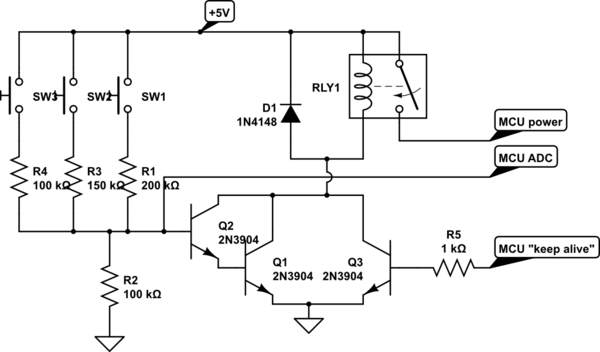
A circuit is being designed that utilizes a combination of switches and resistors to enable a microcontroller to identify which switch has been pressed based on the voltage read, and subsequently perform a switch-specific action. The proposed design incorporates...

This circuit exhibits an exceptionally fast high-frequency response, as demonstrated by applying a 100 kHz square wave to the input. All graphs were produced using Tina Pro. The circuit's design is optimized for high-frequency applications, showcasing rapid response times that...
Arduino Mega 2560 Board tutorials, projects, drivers, schematic, and complete information. The Arduino Mega 2560 is a microcontroller board based on the ATmega2560. It features 54 digital input/output pins, 16 analog inputs, 4 UARTs (hardware serial ports), a 16 MHz...

The first part of this two-part article on paralleling eGaN FETs introduced five basic designs that utilized four EPC2001 (100 V, 25 A) paralleled devices per switch in a half-bridge configuration, accompanied by experimental validation. The second part demonstrates...
The input transistor Q2 is an N-channel JFET. Each specific JFET establishes a particular output bias voltage, necessitating the selection of the JFET from various devices to achieve the desired bias value. Fortunately, due to the low current involved,...