
40 meters CW Transceiver


The QRP transceiver described is a compact and efficient design tailored for amateur radio enthusiasts operating within the 40-meter band. The project is structured into two primary modules: the receiver (RX) and the transmitter (TX), allowing for modular assembly based on user preference and skill level.
The receiver utilizes a superheterodyne architecture, which is known for its excellent sensitivity and selectivity. This design choice facilitates the reception of both Single Sideband (SSB) and Continuous Wave (CW) signals across the entire 7 MHz band. The absence of an intermediate frequency (IF) stage and automatic gain control (AGC) is a deliberate simplification to reduce complexity, although it necessitates manual sensitivity adjustments during operation, especially under conditions of varying signal strength.
The transmitter circuit is noteworthy for its frequency conversion method, enabling simultaneous transmission and reception on the same frequency via a single Voltage-Controlled Oscillator (VFO). The automatic RX/TX switching circuit enhances operational convenience by allowing for seamless transitions between modes. The transmitter employs two transistors configured for class A and class AB operation, optimizing power efficiency and linearity. The output stage is designed to deliver a power output of approximately 150-200 mW into a 50-ohm load, which is suitable for QRP operations.
Coil design is critical for the RF performance of the transmitter. Both L1 and L2 coils, constructed from enameled wire on T44-2 Amidon toroids, are tailored to ensure efficient RF filtering and amplification. The careful biasing of the transistors and the use of links wrapped around the coils contribute to the stability and overall performance of the amplifier stages.
The physical layout is also an important consideration. The transceiver is designed to fit onto two single-sided printed circuit boards measuring 100x66 mm, which can be mounted on a metallic base and housed within a metal cabinet for shielding and durability. User interface components, such as the tuning potentiometer and gain control, are strategically placed on the front panel for ease of access. The inclusion of a frequency display and appropriate connectors for power, antenna, and audio output further enhances usability.
Overall, this QRP transceiver project exemplifies a well-thought-out design that balances performance, simplicity, and user-friendliness, making it an attractive option for amateur radio operators interested in building their equipment.This project describes a little QRP transceiver full legal power” (5 W at 12 V) for the 40 meters band. The RIG may be built in a gradual manner, in fact it is divided in two main modules, or you may also complete only the RX module.
The RX section is designed so as to allow receiving both SSB and CW signals on the whole 7 MHz band. The tuning may be done using only an HF receiver, but if you have at your disposal a frequency meter and a signal generator, you could do a better job.
If you are interested in further informations, or to get the PCB masters, please contact me at my E-mail box. The transceiver is composed by two single sided printed boards 100x66 mm. These should be fixed on a metallic ground base, and possibly enclosed in a little metal cabinet. On the front panel you may place the tuning potenziometer (a 10 turns model or a single turn device with a reductor gear) and the gain control. The frequency reading may be obtained with a 200 µA panel connected to the tuning pot. The Key and earphone jacks, like the power and antenna connectors may be housed on the back panel. You may give a nice look to the panel by drawing a 1:1 mask with a common graphic tool (I use the MS POWERPOINT), and then printing it on a self-adhesive transparent.
The whole process may seem to be a little laborious but the result is very attratctive. The Receiver circuit It uses a classic superetherodyne design, for simplicity purpose I didn't implement an IF stage with a related AGC circuit, this is a compromise choice and implies some manual sensitivity adjusting in presence of strong QSB. The overall sensitivity and selectivity are very good and so also the capability to handle strong overloading signals, proving the effectiveness of the preselector stage and XTAL filter.
The Transmitter circuit I employed a frequency conversion approach, in this manner it is possible to receive and transmit on the same frequency using a single VFO. An automatic RX/TX switching circuit implements the full breakin and monitor function. The assembly is not particularly critical, however some care must be dedicated to align carefully the amplifier stages, so as to avoid possible instability.
It employs two transistors (TR3-TR4), the first works as a class A amplifier, the output of this stage is tuned by the L1-CV1 circuit, so as to filter the spurious signals produced by the mixer. The second transistor is biased by a resistor divider, so as to obtain a class AB working with a current drain ranging from 40 mA (no signal) to 60-65 mA (full power).
The coupling between the stages is made by links wrapped on the tuning coils. This stage can deliver an output power of about 150-200 mW on a 50 ohm load, a little heat sink is needed for TR4. The L1 and L2 coils are made by 33 turns of of enameled 0.40 mm wire on a T44-2 Amidon toroid. L1 has a tap at the 10 th turn from the ground and a link made by 3 turns of of plastic insulated wire.
L2 has a tap at the 7 th turn from the supply side and a link made by 2 turns of of plastic insulated wire. Both the links are wrapped on the coils starting from the cold side. 🔗 External reference
Related Circuits
The three-amplifier implementation of the state-variable filter in Figure 1 provides for second-order bandpass, highpass, and lowpass responses. The strength of the circuit, however, is in the bandpass response (VOUT/VIN), in which it's easy to achieve high gain (G)...
DDS VFOs are highly compatible with single conversion SSB radios, including models such as the Codan 6801, 6924, 7727, and 8121, as well as the AWA Teleradio 110H. Additional details regarding suitable Codan radios can be found on the...
The Multimeter Clock consists of three multimeters, the first meter displays hours, the second displays minutes and the last displays seconds. A 16F628A PIC microcontroller keeps track of time and outputs a calculated current to each meter to display...
In general, the transceiver switches the 4-element 1500 ohm xtal BPF ends between the inputs and outputs of the two SA602s to reverse the signal flow for R/T operation. Since no IF amplifier is used in the design, 20...
Due to their speed, accuracy, effectiveness, and cost-efficiency, infrared (IR) digital thermometers have supplanted traditional mercury thermometers. An ear digital thermometer utilizes a thermopile sensor to measure the infrared heat emitted by the eardrum, which correlates with the temperature...
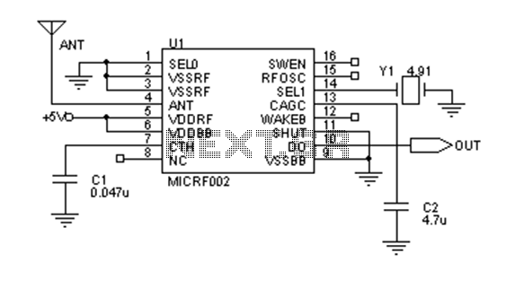
Early transmitters using LC oscillators experience significant frequency drift. The introduction of Surface Acoustic Wave (SAW) devices addresses this issue, providing substantial frequency stability comparable to crystals. These devices can achieve fundamental frequencies in the hundreds of megahertz or...