
DPPs program key parameters of bandpass filter

The described circuit utilizes a three-amplifier configuration to achieve versatile filtering characteristics, specifically focusing on second-order responses. The state-variable filter design is notable for its ability to provide multiple output types—bandpass, highpass, and lowpass—through a single configuration. The bandpass response is particularly emphasized due to its capacity for high gain (G) and a high quality factor (Q), both of which are critical for applications requiring precise frequency selectivity.
In practical applications, the ability to control the center frequency (f0) and gain (G) of the bandpass filter using digitally programmable potentiometers (DPPs) enhances the circuit's functionality. This feature allows for dynamic adjustments, making the filter adaptable to a variety of signal processing tasks. The integration of DPPs can facilitate real-time tuning of the filter, enabling it to respond to changing signal conditions or specific application requirements.
The circuit typically employs operational amplifiers configured in a feedback arrangement to achieve the desired filter characteristics. Each amplifier plays a role in shaping the frequency response, ensuring that the output maintains the necessary phase and amplitude characteristics across the desired frequency range. The design also allows for easy implementation of additional features, such as gain control and frequency modulation, further increasing its versatility in electronic systems.
In summary, the three-amplifier state-variable filter is a robust solution for applications requiring selective signal processing, with the added benefit of programmability through DPPs, enhancing its adaptability and performance in various electronic applications.The three-amplifier implementation of the state-variable filter in Figure 1 provides for second-order bandpass, highpass, and lowpass responses. The strength of the circuit, however, is in the bandpass response (VOUT/VIN), in which it`s easy to achieve high gain (G) and high Q.
These two characteristics are important in applications in which selectivity is a key parameter in the filter. The application value of the circuit becomes even greater when DPPs (digitally programmable potentiometers) control and vary the bandpass filter`s center frequency, f0, and passband gain, G.
🔗 External reference
Related Circuits
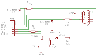
There are various types of AVR programmers available in the market; most utilize a parallel port, a serial port (COM port), or USB connectivity. However, these devices can be quite expensive, making them inaccessible for hobbyists. Therefore, a cost-effective...
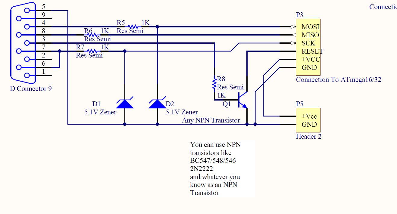
ISP programmer with circuit diagram for AVR Atmega32 microcontroller. This ISP burner circuit is an adaptation of the Pony programmer and uses PonyProg software. The ISP (In-System Programming) programmer designed for the AVR Atmega32 microcontroller facilitates the programming of the...
Stationary - MOPLL & Silicon Tuner TUA6020 2 Band TV Tuner Mixer-Oscillator-PLL with balanced IF-Amplifier. The TUA6020 device integrates a digitally programmable Phase Locked Loop (PLL) with a mixer-oscillator block that includes two balanced mixers and oscillators suitable for...
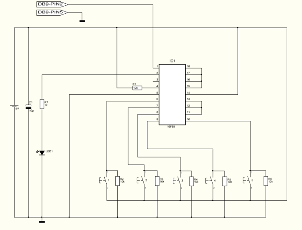
This project can be utilized for various purposes, with one of the most common applications being the interfacing of a keypad for electronic projects. While several pre-made keypads are available on the market, they typically operate with matrix connections,...
The controllable multivibrator, as illustrated in figure 14-40, consists of a 555 timer along with resistors RA, RP1, and capacitor C1. The oscillation frequency is influenced by the control voltage applied to pin 5. This control voltage is determined...
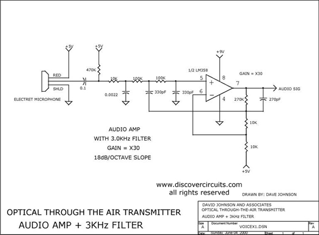
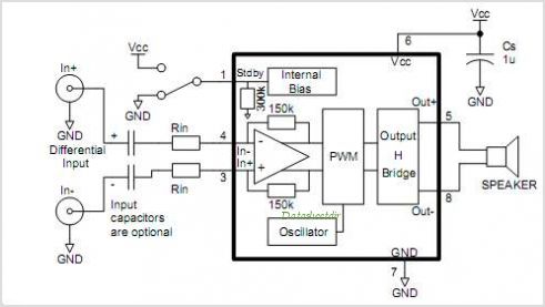
Audio amplifier with a 3 kHz filter. This circuit serves as the audio amplification section for a complete optical transmitter. It amplifies and filters voice audio signals from an electret microphone. The audio amplifier circuit is designed to enhance the...