
4017 based sequencer

The clock section of the circuit serves as the foundation for timing and sequencing operations. The internal oscillator's speed is adjustable through a knob, with the added functionality of voltage control via the Speed In input, allowing for dynamic modulation of the oscillator frequency. The Clock In input enables the integration of external clock signals, providing flexibility for synchronization with other devices or sequencers.
The sequencer consists of 10 discrete steps, each featuring a control voltage (CV) input that ranges from +9V to 0V, allowing for precise control over pitch and other parameters. Each step is equipped with an LED indicator, providing visual feedback on the active step. The individual CV and Gate outputs enable connection to various modules, facilitating complex signal routing and modulation.
The three-way switch is a critical component, offering multiple operational modes for each step. Users can choose to activate or deactivate a step or configure a step to act as a reset point, enhancing the sequencer's versatility. This design choice allows for creative sequencing possibilities, including the option to create single-step sequences or reset configurations.
Hold and Reset inputs are integral for performance and control. The Hold input allows a step to be sustained indefinitely when receiving a high gate signal, enabling the creation of sustained notes or effects. The Reset input returns the sequence to its initial state, providing a straightforward means to restart the sequence. Both inputs are designed to accept high gate signals from various sources, ensuring compatibility with a wide range of control voltages.
The Master CV and Gate outputs aggregate the outputs from all steps, allowing for centralized control of pitch and gate signals. This design enhances patchability, enabling users to connect the master outputs to external modules, such as oscillators, for synchronized performance.
Overall, the schematic design emphasizes flexibility and user control, making it suitable for a variety of musical applications. The insights gained from the design process, particularly regarding the 555 timer's operation and capacitor selection, contribute to a deeper understanding of oscillator behavior and potential applications in modular synthesis. The design encourages experimentation and adaptation, inviting users to explore the full capabilities of the sequencer within their modular systems.Below that is the clock section. The knob controls the internal oscillator`s speed, and that can be voltage-controlled via the `Speed In` input. Or, you can insert your own clock signal via the `Clock In`. This is slightly unusual, but I think having the option is useful. -Then you get to the 10 steps. Each has a CV control (+9V to 0V), LED step i ndicator, and individual CV and Gate outputs. You`ll also note the three-way switch. This can turn on or off each step, or can set that step to reset the sequence (so you can literally have a 1-step sequence if you want, or you can switch the 9th step to reset and have a musically normal 8-step sequencer) -After that you have Hold and Reset inputs. Hold will holda step indefinitely given a high gate signal. Reset will reset the sequence to step 1. Either can be controlled with anything that can create a high gate signal, even a +9V CV signal. Each also has an attenuated input, should you need it. -Master CV and Gate are just like the individual CV and Gate, but each step outputs to it. This way you can, say, patch the master CV to an oscillator and sequence the pitch. You may ask why I did what I did here, and it`s mainly for maximum patchability. It`s totally possible you`d never use parts of it, but I`m sure you can see the usefulness of each part (assuming you know how most sequencers work nowadays) This schematic isn`t entirely accurate, mainly because my version of LTSpice doesn`t have some of the parts.
Given the description you can build it, though. You`ll have to pay attention to your exact 4017 and its outputs, otherwise this schematic will be a bit wonky for you. Oh, and of course, you`ll want to connect your 3-way switch`s 3rd setting to your reset pin if you want that.
You could also just patch a step`s gate output to the reset input and use a normal on/off switch. I actually learned something useful with this project (as I usually do): the 555 timer`s speed is controlled not only by the resistor, but the capacitor between pins 1 and 2. The shunting cap is only for precision and can be just about any size (at least, between 1uF and 10nF).
Using a 1uF cap, like in this circuit, you can get a frequency range of. 5Hz to 1500Hz. With my normal oscillator (which will probably be changed now) used 10nF caps, and bottomed out in the hundreds Hz range and went out of the audio range. That`s kinda useless given that it`s the main source of sound in a synthesizer. Also, given this new knowledge, I think I know how to create an LFO module: just use the clock circuit from this, usemy oscillator`s waveshaping section, add voltage control, and bam!
» Instant LFO module. Though I do wish I knew how Pittsburgh Modular got such an insane frequency range with their Oscillator. Oh, and for those of you looking for pics of my modular, well, it doesn`t exist. I don`t have all the parts or skills to actually build these as modules. Given a number of pots, jacks, and the ability to work sheet metal, then I`ll start building them. 🔗 External reference
Related Circuits
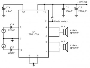
The provided schematic represents a car stereo amplifier circuit that can be utilized in cars or other vehicles. The circuit is based on the TDA1553, which is a Class-B audio amplifier. This circuit is straightforward, consisting solely of the...
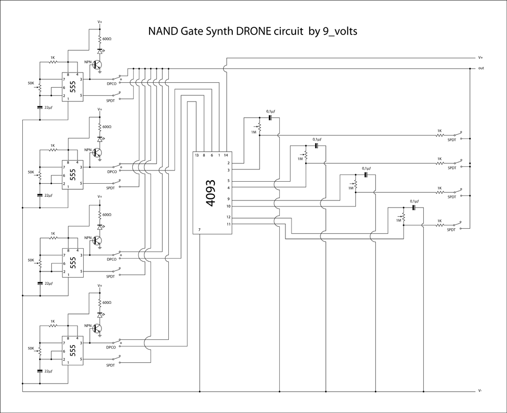
This is a brief jam session to explore the capabilities of a recently completed step sequencer. This device is quite enjoyable and expands creative possibilities. A detailed post with the circuit and instructions for building it will be provided...
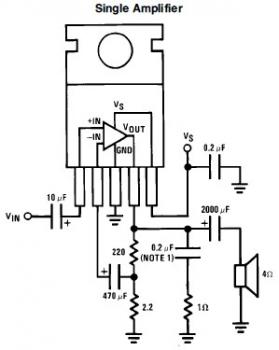
This is a simple mini audio amplifier circuit built around a single LM383 integrated circuit, along with several discrete components to support its operation. The circuit is capable of delivering approximately 7W of audio output. It can be constructed...
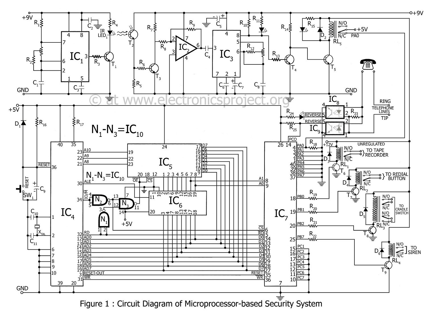
A microprocessor-based home security system project. This advanced security system not only notifies the user but also alerts the police immediately. In the 8085 microprocessor-based home security system, control is exercised over a siren, telephone (via cradle and redial...
The bi-directional sequencer employs a 4-bit binary up/down counter (CD4516) along with two "1 of 8 line decoders" (74HC138 or 74HCT138) to create the well-known "Night Rider" display. A Schmitt Trigger oscillator generates the clock signal for the counter,...
Field bus technology and intelligent instrument technology are currently two of the most rapidly evolving technologies in automation and control. In the realm of field bus technology, the CAN bus has established itself as a relatively fast communication standard...