
Simple Sixteen Stage Bi-Directional LED Sequencer

The bi-directional sequencer circuit is a versatile and engaging design that effectively demonstrates the principles of digital counting and display control. The use of a CD4516 counter allows for seamless counting in both directions, enhancing its functionality for various applications. The integration of two 1 of 8 line decoders (74HC138 or 74HCT138) enables the circuit to control multiple outputs, creating a visually appealing "Night Rider" effect that can be utilized in decorative lighting or signal displays.
The Schmitt Trigger oscillator plays a crucial role in generating a stable clock signal for the counter. The adjustable 500K potentiometer allows users to modify the speed of the display, providing flexibility in the design. The choice of the 74HC14 Schmitt Trigger inverter is significant, as it ensures compatibility with the TTL input levels, thereby enhancing the reliability of the circuit.
The SET/RESET latch mechanism is pivotal in determining the counting direction. When the counter reaches its maximum count, the output at pin 7 triggers the latch to switch the counting direction from up to down, allowing the display to reverse its sequence. The ability to reset the latch when the counter hits the minimum count ensures continuous cycling of the display.
The parallel connection of the three least significant bits to both decoders allows for simultaneous control of multiple outputs, while the most significant bit determines which decoder is active at any given time. This configuration maximizes the efficiency of the circuit and simplifies the control logic.
For applications requiring higher power outputs, the circuit can interface with 12V/25W lamps through the use of transistors. This feature expands the circuit's potential applications in real-world scenarios, such as in automotive lighting or large-scale display systems, where higher voltage and current handling capabilities are necessary. The detailed interfacing instructions provided in the relevant section ensure that users can implement this feature safely and effectively.The bi-directional sequencer uses a 4 bit binary up/down counter (CD4516) and two "1 of 8 line decoders"74HC138 or 74HCT138) to generate the popular "Night Rider" display. A Schmitt Trigger oscillator provides the clock signal for the counter and the rate can be adjusted with the 500K pot.
Two additional Schmitt Trigger inverters are used as a SET /RESET latch to control the counting direction (up or down). Be sure to use the 74HC14 and not the 74HCT14, the 74HCT14 may not work due to the low TTL input trigger level. When the highest count is reached (1111) the low output at pin 7 sets the latch so that the UP/DOWN input to the counter goes low and causes the counter to begin decrementing.
When the lowest count is reached (0000) the latch is reset (high) so that the counter will begin incrementing on the next rising clock edge. The three lowest counter bits (Q0, Q1, Q2) are connected to both decoders in parallel and the highest bit Q3 is used to select the appropriate decoder.
The circuit can be used to drive 12 volt/25 watt lamps with the addition of two transistors per lamp as shown below in the section below titled "Interfacing 5 volt CMOS to 12 volt loads". 🔗 External reference
Related Circuits
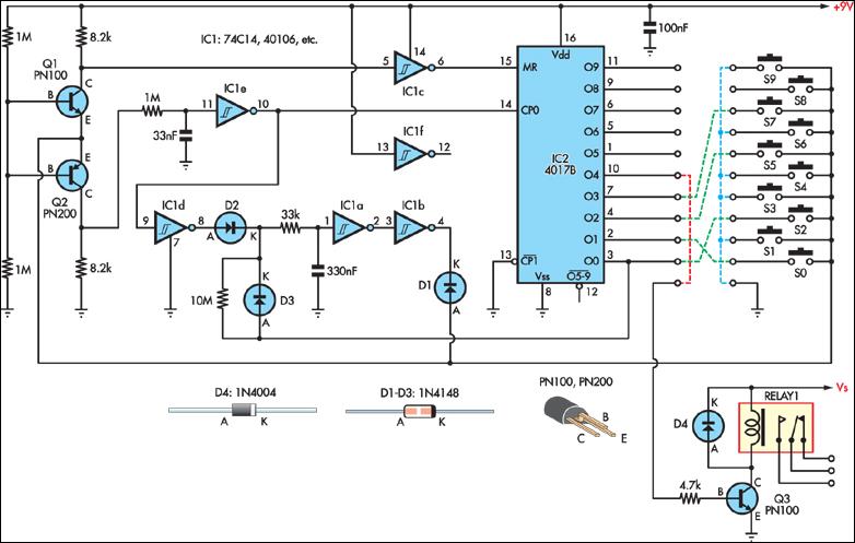
This simple combination lock accommodates codes from 1 to 9 digits long, with the only restriction being that the same digit cannot be used twice. The circuit is designed for a 4-digit code, illustrated by the example "2057". Any...
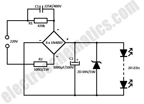
This white LED floodlight illuminates your porch with cool white light. The circuit features a simple and energy-saving design, with a low current consumption. The LED floodlight circuit typically consists of a power supply, a control circuit, and the LED...
This week’s project involves a simple 4-step sequencer utilizing a 4017 decade counter chip. The fundamental schematic is based on a circuit that employs a 555 timer as a clock source. Modifications include using the outputs of the 4017...
A dimmer for individual LED bulbs. LEDs (light emitting diodes) are very sensitive components; exceeding their rated current or voltage can drastically reduce their lifespan from over 50,000 hours to mere microseconds. LEDs are current-driven, meaning that the intensity...

The servo motor is a type of traditional motor that serves as the execution component in automated devices. Its most significant characteristic is its controllability; when a control signal is applied, the servo motor rotates, with its speed being...
The circuit operates as illustrated in Figure 5-2a. It includes an alarm switch (S). When switch S is pressed, relay K is activated, which closes two normally open contacts. This action triggers the alarm bells. The alarm continues to...