
4017 IC For Three Hour Timer

The circuit utilizes the 4017 decade counter IC to control the charging process. The 4017 IC is capable of counting pulses and can be configured to generate a specific output after a predetermined time interval. In this application, it is employed to manage the charging duration of a battery, ensuring that it is charged for exactly three hours.
The setup involves connecting the 4017 IC to a clock source, which can be derived from a timer circuit or an oscillator. The output from the 4017 IC can be connected to a relay or a transistor switch that controls the connection between the battery and the charger. When the circuit is powered on, the 4017 counts up to the set limit, which corresponds to the desired charging time. Upon reaching the count that signifies three hours, the output pin triggers the relay or transistor, effectively disconnecting the battery from the charger to prevent overcharging.
Additional components may include resistors and capacitors to stabilize the circuit and ensure accurate timing. A power supply is also necessary to provide the required voltage to the 4017 IC and other components. This arrangement allows for efficient battery management, promoting battery longevity and safety by preventing excessive charging.Function: made for battery charging time of three hours. Once the charging time is up the battery will be disconnected from the charger. Component: 4017 IC, .. 🔗 External reference
Related Circuits
This circuit is designed to indicate the power output level of any audio amplifier. It is simple, portable, and displays three power levels that can be set to any desired value. The circuit operates by utilizing a combination of resistive...
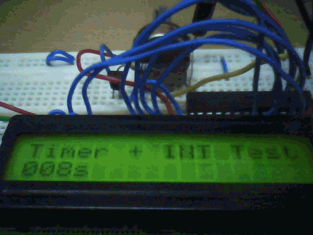
There are 4 timers in PIC18 which are timer0 to timer3. Timers are used when precise timing event need to be generated. Timers are usually used in conjunction with interrupt to keep the timing accurate. This guide will show...
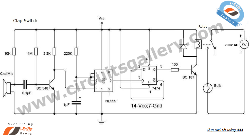
This is an intriguing 555 timer circuit designed to entertain and engage individuals while studying electronics in educational settings. Commonly referred to as a clap switch circuit, it operates as a sound-controlled flip-flop. This sound-controlled light can also function...
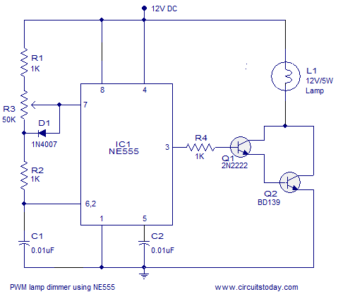
A simple PWM lamp dimmer using the NE555 timer IC. The 555 timer IC is configured as a variable duty cycle astable multivibrator to control the brightness of the lamp. The described circuit utilizes the NE555 timer IC, a versatile...

This circuit is designed as a countdown timer utilizing a countdown calculation. It employs the 555 integrated circuit (IC) as the primary control element. The 555 IC functions as a counter and a transistor switch to activate a relay...
The 555 IC is a widely used component for timer circuits. By incorporating an integrator circuit, it is possible to extend the timing period of the 555 IC timer while maintaining a reasonable capacitor size. The 555 timer IC is...