
Three-Level Audio Power Indicator circuit

The circuit operates by utilizing a combination of resistive voltage dividers and LED indicators to provide a visual representation of the amplifier's output power. The design includes three distinct thresholds, each corresponding to a specific power level. These thresholds can be adjusted to meet the requirements of varying audio amplifiers, allowing for flexibility in its application.
The input signal from the audio amplifier is fed into a voltage divider, which scales the voltage down to a manageable level suitable for processing. The output from the voltage divider is then compared against preset reference voltages using a comparator circuit. Each comparator output drives an LED indicator that illuminates when the corresponding power level is exceeded.
The circuit can be powered using a standard battery or a DC power supply, enhancing its portability. The use of low-power components ensures minimal energy consumption, making it suitable for extended use in various environments. Additionally, a calibration feature may be included, allowing users to fine-tune the threshold levels to match the specific characteristics of the audio amplifier being monitored.
Overall, this power output level indicator circuit is an effective tool for audio professionals and enthusiasts, providing real-time feedback on amplifier performance and ensuring optimal operation within safe power limits.This circuit is intended to indicate the power output level of any audio amplifier. It is simple, portable, and displays three power levels that can be set to any desired value.. 🔗 External reference
Related Circuits
For some time, a method to measure laser power has been sought without incurring significant expenses on a power meter. Initially, constructing such a device may seem unfeasible. To create a cost-effective laser power measurement system, one approach involves utilizing...
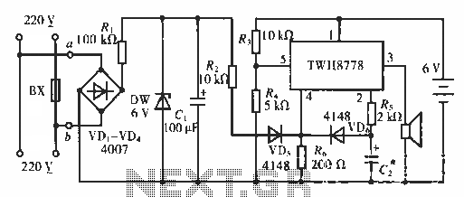
The circuit functions as an AC blown fuse alarm. When the fuse (BX) is intact, 220 V AC voltage passes through a bridge rectifier composed of diodes VD1 to VD4. Resistor R1 limits the current, and the output is...

The circuit functions as a constant voltage source, modified by feedback components R2 and R3 to maintain a stable output voltage. The ZN424E output must be at least 2 volts above the negative rail, with the load connected to...
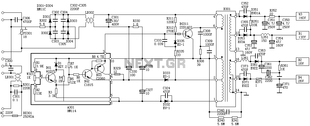
Oscillation: The positive terminal voltage of C310 is approximately 300V. The resistors R311 and R312 are connected to the switch BG311 at the B pole, while the B301 winding via the switching transformer (4) and (6) is connected to...
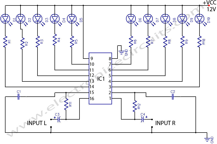
LED stereo sound level indicator for audio amplifier. Many circuits can be designed as level indicators by using a comparator IC or transistors, but... The LED stereo sound level indicator serves as a visual representation of the audio signal levels...
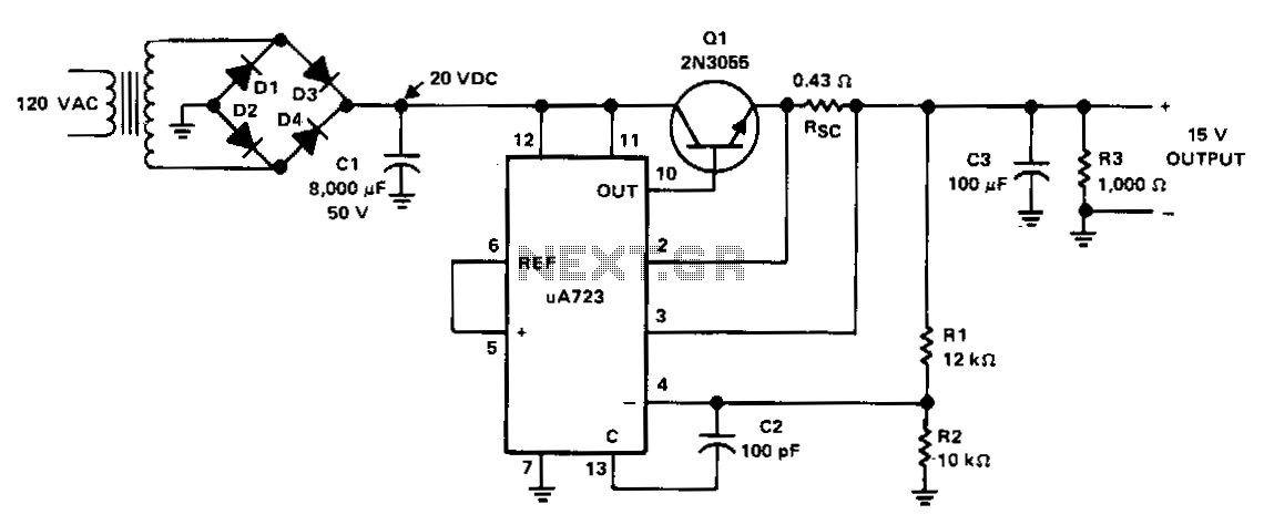
The power supply receives +20 VDC from the rectifier/filter section. This voltage is applied to pins 11 and 12 of the uA723 voltage regulator, as well as to the collector of the 2N3055 series-pass transistor. The output voltage is...