
4060IC For Timed Beeper Electronic

The 4060 IC is a versatile integrated circuit that combines a binary counter and an oscillator, making it ideal for timing applications. In this circuit, the 4060 IC is configured to generate a specific time delay, which can be used to activate a beeper or buzzer. The oscillator section of the 4060 is typically set up with external resistors and capacitors to determine the frequency of oscillation, which directly influences the timing interval.
In a typical configuration, the circuit may include a power supply connected to the Vcc pin of the 4060, while the ground pin is connected to the circuit's common ground. The timing components, including resistors and capacitors, are connected to the appropriate pins of the 4060 to set the desired timing duration. The output from one of the counter stages can be used to trigger a transistor, which in turn drives a beeper or buzzer, providing an audible signal when the time limit is reached.
Additionally, the circuit can include a reset mechanism that allows the timer to be restarted, enabling repeated use in games. The design can be further enhanced by incorporating adjustable timing components, such as potentiometers, to allow users to modify the response time according to their preferences.
Overall, this 4060 IC-based timed beeper circuit provides an efficient solution for implementing time-sensitive tasks in various electronic applications, particularly in game settings where timely responses are crucial.This circuit shows about 4060IC For Timed Beeper Electronic Circuit Diagram. Features: suitable for table games requiring a fixed time to answer a .. 🔗 External reference
Related Circuits
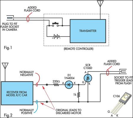
A radio-controlled electronic flash is an essential tool for any photographer's kit, frequently utilized by professionals. For instance, a wedding photographer may position one behind the bride to illuminate her gown and veil without visible wires in the shot....
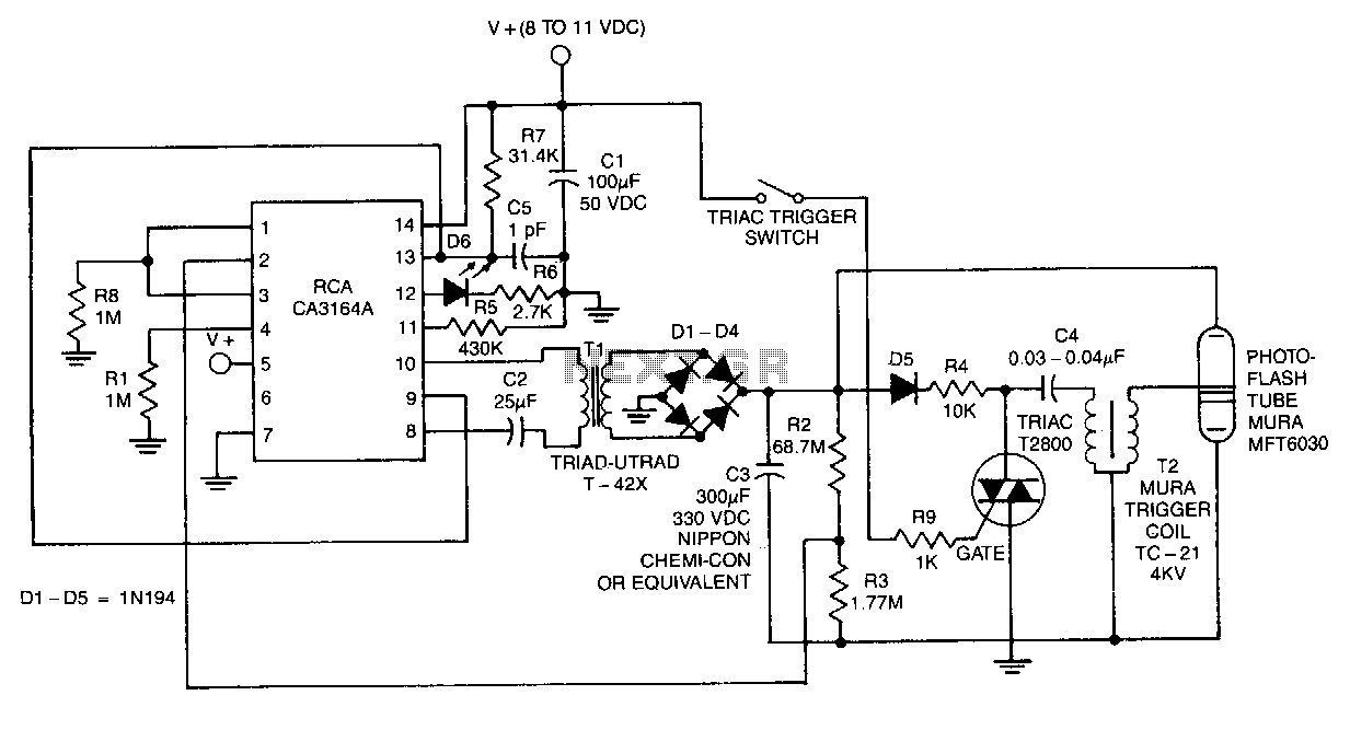
The CA3164A BiMOS control chip operates with a standby current consumption of less than 15 pA while delivering 100 mA of chopped current to the de-to-de converter during the energy-reservoir charging cycle. This chip drives the primary of transformer...
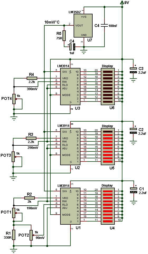
The electronic thermometer schematic features the LM35DZ temperature sensor. Various types of LM35 integrated circuits exist, but the LM35DZ was selected for this project due to its affordability and availability. This sensor operates within a temperature range of 0°C...
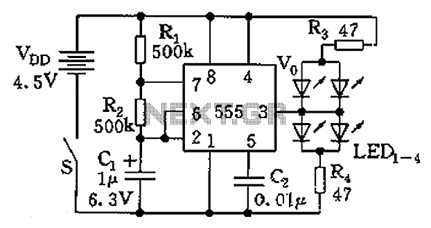
The circuit consists of a 555 timer and a light-emitting diode (LED) array. The 555 timer, along with resistors R1, R2, and capacitor C1, forms an astable multivibrator configuration. The oscillation frequency is calculated using the formula f =...
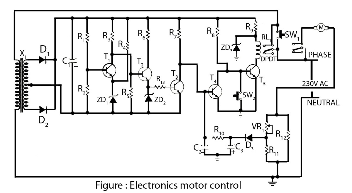
Electronics motor control is a simple circuit made without an integrated circuit (IC). It involves the electronic control of an AC motor and includes a circuit diagram along with a description of the electronics motor controller. The electronics motor control...
A keyboard key functions by establishing an electrical contact between the surface of the keyboard and the underlying circuit when the keytop area is pressed. This mechanism was utilized by some home computers in the early 1980s and has...