
555 jewelry small electronic circuit diagram

The described circuit utilizes the well-known 555 timer IC, which functions in an astable mode to produce a continuous square wave output. The output frequency is determined by the values of R1, R2, and C1. In this configuration, R1 and R2 are connected in series with the discharge pin and threshold pin of the 555 timer, while C1 is connected between the threshold pin and ground. The charging and discharging of C1 through R1 and R2 creates a repeating cycle of high and low output states, resulting in a flashing effect for the connected LEDs.
The choice of resistors R3 and R4 is crucial as they limit the current flowing through the LEDs, preventing damage due to excessive current. The selection of different colored LEDs allows for a variety of visual effects, as each LED may have different forward voltage requirements and luminosities. The circuit can be powered by a standard power supply, typically in the range of 5V to 15V, depending on the specifications of the 555 timer and the chosen LEDs.
To enhance the circuit's performance and reliability, it is advisable to use decoupling capacitors across the power supply pins of the 555 timer to filter out any noise that may affect the timing accuracy. Additionally, incorporating a potentiometer in place of R2 could allow for adjustable frequency settings, providing further versatility in the flashing rate of the LEDs. Overall, this circuit is an effective and straightforward implementation of a flashing LED display using a 555 timer, suitable for various applications in decorative lighting and signaling. Circuit as shown by 555 and the light emitting tube. 555 and R1, R2, C1 composition astable multivibrator, the oscillation frequency f 1.44/(R1 + 2R2) C1, the vibration frequen cy of about 2Hz, flashes twice per second. If LED1 ~ LED4 choose different colors of light-emitting diodes, add luster. R3, R4 current limiting resistor.
Related Circuits
The following circuit illustrates the use of a 555 integrated circuit (IC) for an infrared (IR) remote control extender circuit. Features include support for 850 nm and 950 nm signal wavelengths, along with the capability to generate control pulses. The...
At the beginning of the design process, the designer must determine which circuit structure is appropriate for a specific purpose. During this phase, numerical and symbolic analysis are of limited utility. There are no numerical values available for conventional...
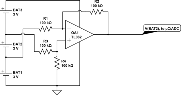
Utilize a high-performance microcontroller (Piccolo TMS320F28035, 12-bit resolution, +/- 4 LSB offset, +/- 60 LSB gain) to measure the voltage across stacked battery cells and control related analog electronics for charge equalization. The microcontroller will also save data in...
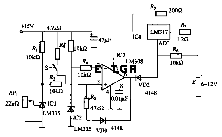
When fast charging a nickel-cadmium battery, the temperature control circuit, as illustrated in the accompanying figure, is designed to monitor the battery temperature to regulate the charging current. The circuit consists of Icl to IC3, which forms the temperature...
This circuit addresses the challenge of transmitting data over a cable that lacks available conductors. The data is modulated using On-Off Keying (OOK) and superimposed on a high-frequency carrier, allowing it to be transmitted over a low-voltage power supply...
It is often necessary to configure a voltage regulator integrated circuit (IC) to provide a higher output voltage than that established by the regulator alone. One method to achieve this is by connecting the common terminal to the midpoint...