
4x15Watt 12volt power audio amplifier

More: These chips can deliver 15 Watt RMS per channel, into 4 Ohm loudspeakers. That's more than enough even for loud home use. The peak power current consumption, when saturating all four channels at the same time, would be 12A, which gives good chances that the computer won't reset from power supply shutdown in such a situation! When using 8 Ohm speakers, the output power and the current consumption are cut down to one half. In fact, that's my situation, because my present speakers are 8 Ohm. The amplifier has a typical distortion in the neighborhood of 0.04%. That's good enough, in my opinion, for a computer sound system, while surely with discrete parts I could have obtained even lower distortion. The gain delivered by the TA8215 is a whopping 50dB, which is MUCH more than needed. So I had to include an attenuator at the input, in order to be able to use the full dynamic range of the sound card.
Here is the complete schematic diagram of one stereo amplifier. Of course, I used two of these for my quad amplifier - and if you want, you can use three to make a 5.1 amplifier! You can click the schematic to get a higher resolution version for printing.
R1 with R2 forms a voltage divider that attenuates the input signal by 24dB. Considering the chip's 50dB gain, that still leaves 26dB overall gain, slightly more than enough to fully saturate the amplifier when the sound card works at maximal output. C1 blocks DC at the preamplifier input. C2 is the ground return of the feedback circuit. These two capacitors need to be in the ratio shown, in order to suppress switching clicks when powering the circuit on and off. The output pins 15 and 16 are connected directly to the speaker, while C7, R6, C8 and R7 provide the proper load phase shifting to avoid high frequency instability.
The lower side of the schematic shows the same circuit repeated, for the other channel inside the chip.
The power supply is decoupled with a rather small 100uF capacitor. That's enough for higher frequency decoupling, and at lower frequencies anyway the large capacitors in the PC power supply are fine. Pins 10 and 17 supply the power amplifiers, while pin 9 provides power to the pre stages. This power is filtered by C3. The power control pin 4 allows to shut down the amplifier, an option not used here, so it's tied to 12V. Pin 1 is a muting input, also not used, and left open.
If you compare this schematic to the one in Toshiba's data sheet, you will notice that it's almost an exact copy, except for R3! Toshiba ties the input ground directly to the output ground. In a PC, this leads to trouble! A computer is a noisy machine. There are quite strong noise currents circulating through ground, for example. If you tie all grounds together, it could well happen that a noisy power ground return from the hard disk takes a route through this power amplifier and the sound card! This makes some nasty noise show up in the speakers.
It's important to understand that the TA8215, like many such chips, has the preamplifier internally separated from the power amplifier. This is very useful to get rid of the described ground loop problems! The input ground is separated from the output ground, except for the 10 Ohm resistor. If this amplifier is used with a signal source that has a floating ground, the resistor is low enough to apply proper power ground to the preamplifier stages, and it works well. However, if the amplifier is installed in a PC, the 10 Ohm resistor is high enough to break up the ground loop that would otherwise form. All sensitive input points, such as voltage divider grounds, feedback returns, and ripple filter capacitor ground, are directly connected to the soundcard ground, and separated by the resistor from the power ground. The result is a very good rejection of noise.
In this system, power supply noise is not audible. However, shorting out the resistor leads to noticeable noise. The inputs are directly soldered to the sound card, right behind its connectors, allowing the connectors to remain available for external devices. The outputs connect to four RCA jacks mounted on a small black plastic project box, installed on the rear of the cabinet. The 12V power and ground are taken from an unused output of the power supply, with the 12V routed through a front panel switch that allows the entire amplifier to be powered off and on. This feature is beneficial for instances when the computer is used as a signal generator, preventing unwanted noises from being output through the speakers.While I would have liked a 4 channel chip with about 20 Watt per channel, the local parts store didn't have any yet, so I opted for two TA8215AH stereo chips, selected by their low price in this particular store. The design? Oh well, there isn't much to it. The circuit I used is almost an exact copy of the circuit suggested in the Toshiba data sheet. I only made a very few changes, but including an important one - the one that makes it possible to use this circuit in a computer, without getting power supply and hard disk noise!
These chips can deliver 15 Watt RMS per channel, into 4 Ohm loudspeakers. That's more than enough even for loud home use. The peak power current consumption, when saturating all four channels at the same time, would be 12A, which gives good chances that the computer won't reset from power supply shutdown in such a situation! When using 8 Ohm speakers, the output power and the current consumption are cut down to one half. In fact, that's my situation, because my present speakers are 8 Ohm. The amplifier has a typical distortion in the neighborhood of 0.04%. That's good enough, in my opinion, for a computer sound system, while surely with discrete parts I could have obtained even lower distortion.
The gain delivered by the TA8215 is a whopping 50dB, which is MUCH more than needed. So I had to include an attenuator at the input, in order to be able to use the full dynamic range of the sound card. Here is the complete schematic diagram of one stereo amplifier. Of course, I used two of these for my quad amplifier - and if you want, you can use three to make a 5.1 amplifier!
You can click the schematic to get a higher resolution version for printing. R1 with R2 forms a voltage divider that attenuates the input signal by 24dB. Considering the chip's 50dB gain, that still leaves 26dB overall gain, slightly more than enough to fully saturate the amplifier when the sound card works at maximal output. C1 blocks DC at the preamplifier input. C2 is the ground return of the feedback circuit. These two capacitors need to be in the ratio shown, in order to suppress switching clicks when powering the circuit on and off.
The output pins 15 and 16 are connected directly to the speaker, while C7, R6, C8 and R7 provide the proper load phase shifting to avoid high frequency instability. The lower side of the schematic shows the same circuit repeated, for the other channel inside the chip.
The power supply is decoupled with a rather small 100uF capacitor. That's enough for higher frequency decoupling, and at lower frequencies anyway the large capacitors in the PC power supply are fine. Pins 10 and 17 supply the power amplifiers, while pin 9 provides power to the pre stages. This power is filtered by C3. The power control pin 4 allows to shut down the amplifier, an option not used here, so it's tied to 12V.
Pin 1 is a muting input, also not used, and left open. If you compare this schematic to the one in Toshiba's data sheet, you will notice that it's almost an exact copy, except for R3! Toshiba ties the input ground directly to the output ground. In a PC, this leads to trouble! A computer is a noisy machine. There are quite strong noise currents circulating through ground, for example. If you tie all grounds together, it could well happen that a noisy power ground return from the hard disk takes a route through this power amplifier and the sound card!
This makes some nasty noise show up in the speakers. It's important to understand that the TA8215, like many such chips, has the preamplifier internally separated from the power amplifier. This is very useful to get rid of the described ground loop problems! I left the input ground separated from the output ground, except for the 10 Ohm resistor. If you happen to use this amplifier with a signal source that has a floating ground, the resistor is low enough to apply proper power ground to the preamplifier stages, and it works well.
But if you install the amplifier in a PC, the 10 Ohm resistor is high enough to break up the ground loop that would otherwise form! All sensitive input points, such as voltage divider grounds, feedback returns, and ripple filter capacitor ground, are directly connected to the soundcard ground, and separated by the resistor from the power ground.
The result is a very good rejection of noise. In my system, I can't hear power supply noise at all, but if I short out the resistor, the noise is all over the place! The inputs were directly soldered to the sound card, right behind its connectors. So the connectors remain available for external devices. The outputs go to four RCA jacks mounted on a small black plastic project box, installed on the rear of the cabinet (barely visible above the Sahne-Nuss chocolate container).
The 12V power and ground were taken from an unused output of the power supply, with the 12V routed a front panel switch that allows to power the entire amplifier off and on. This is a good feature, for the times when I want to use the computer as a signal generator, and don't want the noises to blare out of the speakers!
It's also great for web surfing, to quickly shut down the audio from those web sites that keep forcing undesired background music on you! By the way, mine is a very silent PC! The fans in the power supply and on the CPU run very slowly, in almost complete silence, because I connected them to 5V instead of the normal 12V.
The cabinet fan was eliminated, and the tiny fan on the nVidia video card, which was absurdly noisy, was also eliminated and replaced by a large finned fanless heat sink. The hard disk was foam-mounted inside a sealed black metal box, and this box was in turn foam-mounted in the cabinet!
To ensure adequate cooling of the hard disk, I sprayed the disk and the box (inside and out) flat black, so it can cool by radiation alone! It has worked fine for several years now, so don't tell me that I'm cooking my poor PC! 🔗 External reference
Related Circuits
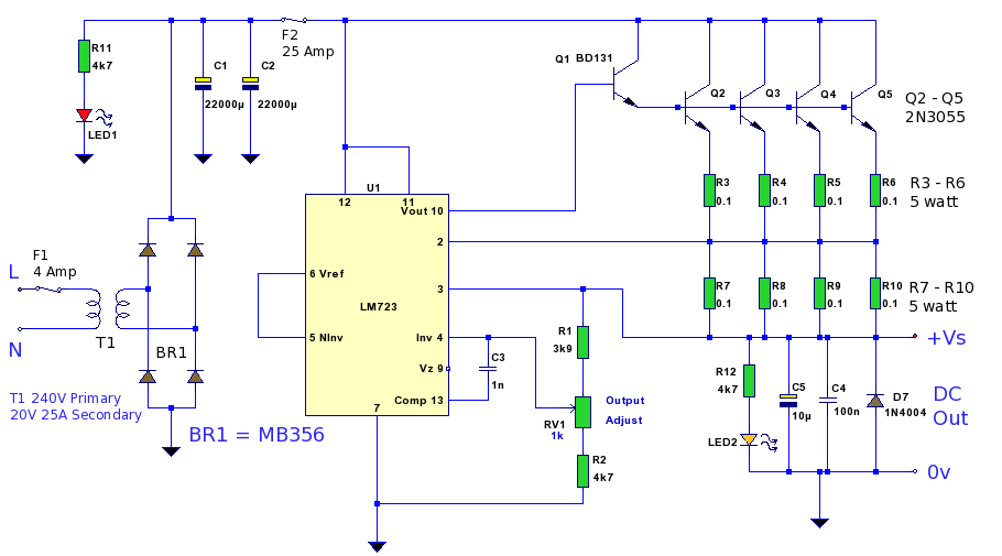
A 12 Volt high current 20 Amp power supply. The output voltage is variable from 12.2 Volt to 14.4V, allowing it to be set for any device requiring voltage and current in that range. This power supply unit (PSU)...
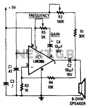
The circuit's frequency oscillation is given by the formula f = 2.8 / [Cix(i1 + i2)]. By utilizing the specified values, the output frequency can be adjusted from 60 Hz to 20 kHz by rotating potentiometer R2. A portion...
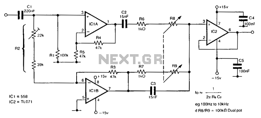
The circuit utilizes a single dual-ganged potentiometer to achieve tuning across a broad spectrum, potentially covering the entire audio range in a single adjustment. The underlying principle is based on the Wien bridge configuration, which is supplied with anti-phase...
Design and dimensioning of active low-pass and high-pass filters using Sallen-Key and multiple feedback topologies. Spice netlist generator. Active low-pass and high-pass filters are essential components in signal processing, allowing specific frequency ranges to pass while attenuating others. The Sallen-Key...
This low-cost project enables audio reproduction from a television without disturbing others. It eliminates the need for wired connections between the TV and loudspeakers. Instead, it utilizes invisible infrared light to transmit audio signals from the TV to the...

A simple audio watt meter circuit or an audio power or audio level meter circuit with diagram and schematics to measure amplifier audio output power in watts. The audio watt meter circuit is designed to measure the output power of...