
Audio Oscillator Ii

The described circuit operates as a frequency oscillator, where the output frequency is primarily determined by the capacitance values of capacitors C1 and C2, as well as the variable resistance provided by potentiometer R2. The formula f = 2.8 / [Cix(i1 + i2)] indicates that the frequency is inversely proportional to the total capacitance present in the circuit, which means that increasing the capacitance will decrease the frequency and vice versa.
In this configuration, IC1 functions as a voltage-controlled oscillator (VCO). The output from IC1 is a square wave, which is characterized by rapid transitions between high and low states. The non-inverting input at pin 3 receives feedback from the output of IC1, allowing for stable oscillation by maintaining the desired reference voltage. Capacitor C1 plays a crucial role in establishing the timing characteristics of the oscillation, as it charges up to the reference voltage and then discharges, creating the square wave.
Capacitor C2 is strategically placed to decouple the output, ensuring that any high-frequency noise generated during the oscillation does not affect the downstream components or the overall performance of the circuit. This decoupling helps maintain signal integrity and improves the reliability of the output signal.
The use of potentiometer R2 provides a convenient method for adjusting the frequency output, enabling flexibility in applications that require different frequency settings. By rotating the potentiometer, the resistance changes, which in turn alters the charging and discharging rates of capacitor C1, effectively varying the oscillation frequency within the specified range of 60 Hz to 20 kHz. This circuit can be utilized in various applications such as timers, tone generators, and signal modulation systems, where precise control over frequency is essential. The circuit"s frequency oscillation is /=2.8/ [Cix(/i + i2)]· Using the values shown, the output frequency can be varie d from 60 Hz to 20 kHz by rotating potentiometer R2. A portion of ICl"s output voltage is fed to its noninverting input at pin 3. The voltage serves as a reference for capacitor CI, which is connected to the noninverting input at pin 2 of the IC. That capacitor continually charges and discharges around the reference voltage, and the result is a square-wave output.
Capacitor C2 decouples the output.
Related Circuits
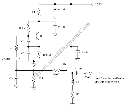
This is a low distortion crystal oscillator circuit. This circuit generates a sine wave that has low phase noise and distortion. This circuit can be used for various applications. The low distortion crystal oscillator circuit is designed to produce a...
Create a simple telephone-based intercom system in a new house. Shouting between rooms is not effective, and using an instant messaging client or FaceTime lacks the immediacy of a voice call. A collection of old wired telephones is available...
This compressor will compress a 25-mV peak-to-peak (p-p) audio signal to a 20-V p-p output, maintaining input levels between 1.5 V p-p and 3.5 V p-p, with a frequency response ranging from 7 Hz to 67 kHz. It is...
This circuit is a conventional Pierce type oscillator that utilizes a JFET. It employs fundamental mode crystals and demonstrates good performance and reliability when a low noise JFET is used. The feedback is regulated by the capacitance C1, which...
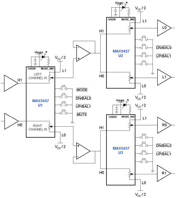
Application circuit using three stereo digital potentiometers to control volume, balance, and fader in a four-speaker configuration with a push-button interface. The application circuit utilizes three stereo digital potentiometers, which are essential components for managing audio levels in a multi-speaker...
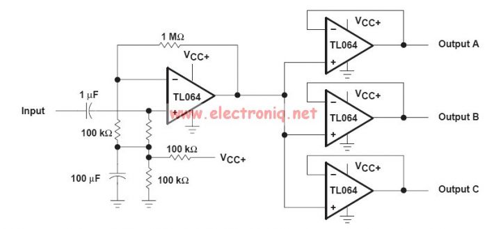
This audio distribution electronic project circuit diagram is designed using the TL064 or TL06 operational amplifiers and some other common electronic parts. The audio distribution circuit utilizes TL064 or TL06 operational amplifiers, which are quad op-amps known for their low...