
5 A stabilized power supply

More: R1 = 3.3 ? 5 watt C1 = V 4700?F/63 C2 = V 10?F/35 C3 = 100nF D1 = 35A T1 = MJ2955 (TO220), MJE2955 (TO3), TIP2955 (TO247) IC1 = 78xx F1 = 5A
The described circuit is a regulated power supply capable of delivering up to 5 Amperes of output current, which is suitable for various applications requiring stable voltage and current. The core of the circuit utilizes a 78xx series linear voltage regulator, which is designed to provide a fixed output voltage ranging from 5V to 24V, depending on the specific model used (e.g., 7812 for 12V output).
To enhance the current handling capabilities, a buffer transistor (T1) is employed, which is typically a power transistor such as the MJ2955. This transistor operates in conjunction with the voltage regulator to ensure that the output current does not exceed 5A. When the load demands more than 200mA, the buffer transistor takes over, effectively limiting the output current to the specified maximum of 5A.
The circuit includes several key components for stability and performance. The resistor R1, rated at 3.3 ohms and 5 watts, is likely used for current sensing or feedback purposes. Capacitors C1, C2, and C3 serve to filter and stabilize the voltage output. C1, rated at 4700µF/63V, acts as a bulk capacitor to smooth out voltage fluctuations. C2, with a value of 10µF/35V, provides additional filtering, while C3, a 100nF capacitor, helps suppress high-frequency noise.
Diode D1, rated at 35A, is included for reverse polarity protection and to prevent back EMF from damaging the circuit components. The fuse F1, rated at 5A, serves as a safety feature to protect the circuit from overcurrent conditions.
To ensure proper operation, the input AC voltage should be at least 5% higher than the desired output voltage. This is crucial for the linear regulator to function correctly, as it requires a minimum voltage differential (headroom) between the input and output. Adequate heat dissipation must be considered for T1, as handling higher output currents generates significant heat; therefore, a suitable heat sink is essential to maintain reliable operation.
Overall, this circuit design is straightforward yet effective for applications requiring a reliable power supply with a stable output voltage and current.This is a simple but powerful nutrition that less than 5 A can deliver. The circuit works by using a normal type 78xx voltage regulator and a buffer transistor. When the output current over 200 mA, then take over the T1, which limits the maximum output current is 5 Amps. The 1978 series regulator is available from 5 to 24 volts. In the place of the xx is the voltage, so 7812 for a 12 volt regulator. Take the AC in 5% higher than the desired output voltage. In that case, one under the wrinkle. MJ is a T1 (E) in 2955. This higher output currents must be well chilled. R1 = 3.3 ? 5 watt C1 = V 4700?F/63 C2 = V 10?F/35 C3 = 100nF D1 = 35A T1 = MJ2955 (TO220), MJE2955 (TO3), TIP2955 (TO247) IC1 = 78xx F1 = 5A 🔗 External reference
Related Circuits
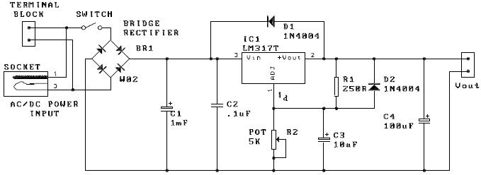
A potentiometer, designated as R2, can be utilized to adjust the desired output voltage. The kit is capable of accepting either AC or DC input through a socket or terminal block. It is advisable to incorporate protection diodes when...
This motor driver delivers power from the capacitor to the motor when the capacitor is charged to 1.75V by the solar cell. After powering the motor, the capacitor. The motor driver circuit is designed to efficiently transfer energy stored in...
Many beginners trying out their skill with QRP TX for the first time have to overcome many problems before they are able to come on the air. One usual complaint is that everything is working fine, but the signal...

This is a circuit for Closed-Loop Automatic Power Control for RF Applications. The circuit utilizes a log detector (AD8318) and a variable gain amplifier (VGA) (ADL5330). The Closed-Loop Automatic Power Control (APC) circuit is designed to maintain a consistent output...
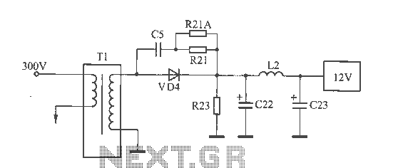
The 12V voltage instability should first be investigated by checking the output section of the switching power supply, as illustrated in the accompanying figure. The secondary winding of the transformer and the switch VD4 have been examined and found...
PowerMan UPS/Inverters manufactures uninterruptible power supplies and voltage regulators. The business was founded in 1993 and was involved in distribution prior to the year 2000. PowerMan specializes in providing reliable power solutions, including uninterruptible power supplies (UPS) and voltage regulators,...