
Closed-Loop Automatic Power Control for RF Applications

The Closed-Loop Automatic Power Control (APC) circuit is designed to maintain a consistent output power level in RF applications, such as transmitters and amplifiers. The system operates by continuously measuring the output power using the log detector AD8318, which provides a logarithmic representation of the input power level. This feature allows for a wide dynamic range and precise power level detection, making it suitable for applications where power fluctuations can significantly impact performance.
The output from the AD8318 is fed into the variable gain amplifier (VGA) ADL5330, which adjusts the gain based on the detected power level. By varying the gain, the VGA can compensate for any changes in output power, ensuring that the desired output level is maintained. The feedback loop formed by the log detector and the VGA allows for rapid adjustments in response to changes in the input signal, providing stable operation under varying conditions.
In terms of implementation, the circuit typically includes additional components such as resistors and capacitors to filter and stabilize the signals. Proper layout and design considerations are crucial to minimize noise and ensure reliable operation, particularly in high-frequency applications. The power supply for the components should also be carefully regulated to avoid introducing additional variations in the output power.
Overall, this closed-loop APC circuit is essential for achieving optimal performance in RF systems, allowing for efficient power management and improved signal integrity.This is a circuit of Closed-Loop Automatic Power Control for RF Applications. The circuit uses a log detector (AD8318) and a VGA (ADL5330). This circuit has a. 🔗 External reference
Related Circuits
It is sometimes necessary for a remote control (RC) model to incorporate switching functionality. Examples include lights on a model boat or the retraction of an airplane's landing gear. A common solution utilizes a servo to operate the switch....
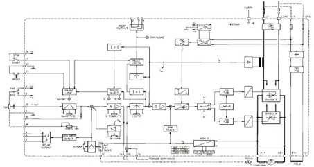
This figure represents the 4Q2 DC Motor Speed Controller Circuit Block Diagram, designed for comprehensive control of conventional shunt-wound and permanent magnet motors with a capacity of up to 75 kW, as specified in the datasheet. This type of...

The sensor is housed in a standard TO-5 or TO-46 package, suitable for measuring surface or air temperatures. Small clip-on heat sinks can be employed to enhance thermal contact. A simple probe can be constructed using heat-shrink tubing and...
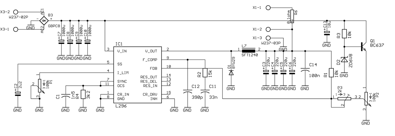
Specifically for the chip used in this circuit, the data is as follows: The oscillator operates at a frequency of 200 kHz, with output noise below 1% (worst case). The maximum current is 4 A at 20 V. The...
The integrated circuit (IC) is a quad 2-input "AND" gate, specifically a CMOS 4081. These gates output a HIGH signal only when both inputs are HIGH. When the key connected to pin E is pressed, current flows through resistor...

Here is a design for a DC motor speed control featuring: Efficient PWM H-bridge MOSFET architecture. Supply (battery) voltage range from 4.2 to 13 volts. High current capacity for driving large motors (65 amps max). Input compatible with standard...