
5 channel graphic equalizer by BC548 transistor

The graphic equalizer circuit functions by providing the ability to adjust specific frequency bands of an audio signal, allowing for tailored sound reproduction. Typically, this circuit consists of multiple band-pass filters, each tuned to a specific frequency range. The output of each filter can be adjusted using potentiometers, which control the gain for that particular frequency band.
The circuit usually comprises operational amplifiers (op-amps) configured as active filters. Each filter section can be designed as a second-order or higher filter to achieve a steeper roll-off and better separation between adjacent frequency bands. The standard configuration may include several bands, such as 31, 15, or 10 bands, covering the audible spectrum from approximately 20 Hz to 20 kHz.
In a typical implementation, the input audio signal is fed into the circuit, and each filter section processes the signal by boosting or attenuating the amplitude of the specific frequency range. The overall output is a composite of all the adjusted signals, providing a customized audio output that compensates for deficiencies in the original audio source or the acoustics of the listening environment.
To ensure optimal performance, components such as resistors and capacitors must be selected with precision, as they determine the center frequency and bandwidth of each filter. Additionally, feedback mechanisms may be employed to stabilize the circuit and reduce distortion, ensuring high fidelity in audio reproduction.
The graphic equalizer circuit is widely used in various applications, including home audio systems, professional sound reinforcement, and music production, making it an essential tool for audio engineers and enthusiasts alike.The graphic equalizer circuit the frequency adjust circuit. For some kinds of audio frequency response is not smooth. The.. 🔗 External reference
Related Circuits
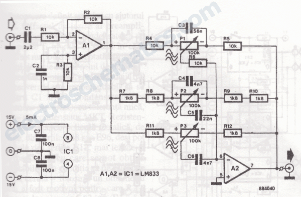
The primary component of this three-band graphic equalizer is the LM833, manufactured by National Semiconductor. The LM833 features very low noise levels and operates with a bandwidth of 15 MHz. The LM833 operational amplifier is designed to provide high-performance audio...
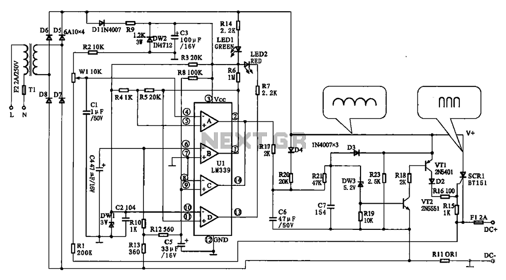
The Chizuru 100Hz channel frequency pulse charging circuit for electric bike batteries is designed to manage the charging process efficiently. It features a step-down transformer (Tl) and a bridge rectifier formed by diodes D5 to D8. The output ripple...
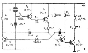
A simple and practical electronic bell circuit can be constructed using the provided schematic diagram. This circuit can function as a doorbell or an alarm system. It utilizes only a few transistors along with several common components. The circuit...
The wah pedal operates before the amplifier but produces a low volume and a scratchy sound when the pedal is rocked back and forth. It functions correctly without the buffer. When placed in front of a Fuzz Face, no...
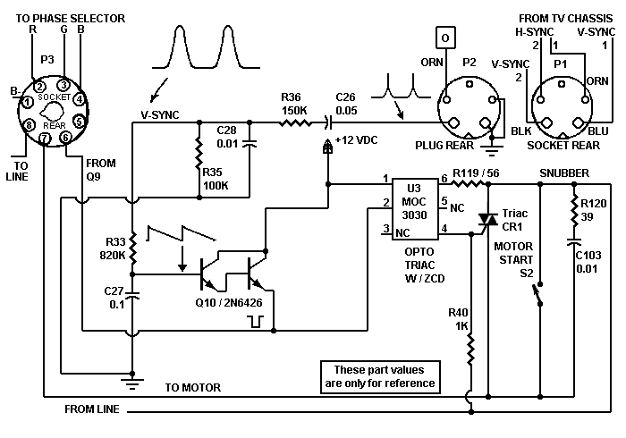
Despite the high impedance of its inputs, the Darlington transistor Q10 generates sufficient current to drive an LED. The inverted output of Q10 powers the internal LED of opto isolator U5, which, in turn, couples to the motor control...
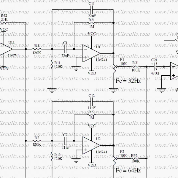
This circuit allows you to equalize the audio signals in ten bands. It uses low-cost op-amps to form a professional equalizer circuit. The heart of the design is a classical band-pass active filter. The U11 acts as an attenuator...