
5-channel low-power programmable sensor signal processor with AD7714 circuit

The AD7714 is a high-performance sigma-delta analog-to-digital converter (ADC) designed for precision measurement applications. The device features an integrated programmable gain amplifier (PGA) that allows for the amplification of small differential signals, making it suitable for use in sensor applications. The differential input configuration enhances noise immunity and improves signal integrity, which is crucial for accurate data acquisition in noisy environments.
The AD780 voltage reference is essential for ensuring that the ADC operates with high precision. By providing a stable +2.5V reference voltage, the AD780 minimizes the effects of power supply variations and temperature fluctuations on the ADC's performance. This stability is critical for applications requiring high accuracy, such as industrial process control and medical instrumentation.
The 3-wire serial interface configuration simplifies communication with microcontrollers or digital signal processors (DSPs). This setup allows for efficient data transfer and control of the ADC, facilitating seamless integration into various digital systems. The use of a quartz crystal or ceramic resonator as the master clock source ensures that the ADC operates at the correct sampling frequency, which is vital for maintaining the integrity of the digitized signal.
In applications where the power supply requirements are stringent, the option to use two independent power sources for the UDD and UDDA terminals provides flexibility in design. This capability allows designers to optimize power consumption and performance based on specific application needs, ensuring that the AD7714 can meet the demands of diverse operational environments.AD7714 Typical application circuit is shown in Fig. UDD, UDDA end of the AD7714 can be connected to + 3V or + 5V power supply. Analog inputs are configured as three differential pair of input terminals. AD780 provides precision + 2.5V reference voltage. The CS non-terminated DGND, AD7714 is configured for 3-wire serial interface. Provide the master clock by a quartz crystal (or ceramic resonator). In some special applications require UDD, UDDA end by two independent power sources to drive.
Related Circuits
A long time ago, when telephones were simple and reliable from an electrical standpoint, telecom operators installed surge protection on all telephone lines at risk from storms. Paradoxically, as modern technology has led to the use of delicate and...
The following circuit illustrates a Mains Remote-Alert Circuit Diagram. Features include simple circuitry, with the transmitted signal being conveyed effectively. The Mains Remote-Alert Circuit is designed to provide a notification system that alerts users about the status of mains power....

This 555 timer circuit temperature monitoring system project can monitor temperature at up to four points. The system allows for the selection of whether the alarm should be triggered when the temperature increases or decreases, depending on the resistance...
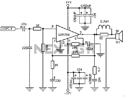
The NS LM4766, launched by a US company, is a two-channel power amplifier integrated circuit. Each channel can output an average power of 40W at an 8-ohm load, with distortion levels lower than 0.1%. It is part of National...
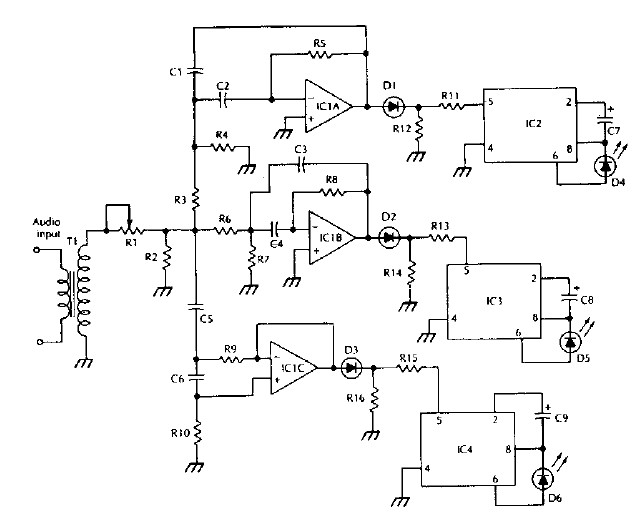
The LM 3909 LED flasher integrated circuit (IC) can be utilized to design various electronic projects. A circuit diagram illustrates the creation of a simple color organ using the LM3909 LED flasher IC. Three active filters process the audio...
Chris from PyroElectro.com has an informative article detailing a do-it-yourself radar system constructed using the PIC18F452 microcontroller. This project is an excellent hobbyist endeavor, although the schematic design is quite complex. The system integrates three primary components to form...