
Infrared Radar Circuit

The radar system operates by utilizing an infrared range sensor that detects objects within its range. The sensor emits infrared light and measures the time it takes for the light to reflect back from an object. This time measurement is then translated into distance, providing information about the proximity of nearby objects.
The PIC18F452 microcontroller plays a crucial role in this system. It receives the output from the IR range sensor and processes the data using its built-in algorithms. The microcontroller is programmed to interpret the distance data and manage the logic required to control the LED array. This allows for the visualization of detected objects, where the LEDs can indicate varying distances based on the sensor readings.
The LED array serves as the output interface, providing a clear visual representation of the radar system's findings. Each LED can light up in different patterns or colors, depending on the distance of the detected object, thus enabling users to gauge proximity effectively. The complexity of the schematic arises from the need to integrate these components seamlessly while ensuring that the microcontroller is programmed correctly to handle the data flow and output.
Overall, this DIY radar system is an engaging project that combines hardware and software skills, providing users with practical experience in working with microcontrollers, sensors, and output devices. Chris from PyroElectro.com has a great article about a do-it-yourself radar system build with PIC18F452. It’s a great hobby project although the schematic is very complicated. This project uses three main devices to create a personal radar system. The IR Range sensor gives output, the pic microcontroller processes it and then displays the output on the led array.
🔗 External reference
Related Circuits

The IR Theremin hardware schematic is notably simple, as the primary input and output devices require minimal connections. This simplicity can be a double-edged sword, as fewer hardware components often lead to increased software complexity. The main components utilized...
The controller circuit illustrated in Figure 15-24 consists of a switch-type Hall integrated circuit DN838 and an astable multivibrator, which is based on the 555 timer IC. This circuit is suitable for various applications, including automatic door opening, delay...
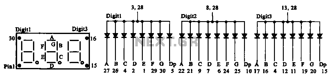
The document presents two types of digital display circuits. The first type (a) utilizes a common anode circuit configuration, while the second type (b) employs a common cathode circuit structure. The common anode display circuit configuration consists of multiple light-emitting...
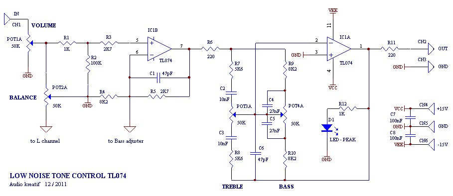
A tone control or pre-amplifier is an amplifier circuit that enhances audio signals. It is important to understand the characteristics, advantages, and disadvantages of various amplifier equipment, as the performance of different amplifiers may not show significant differences. The...
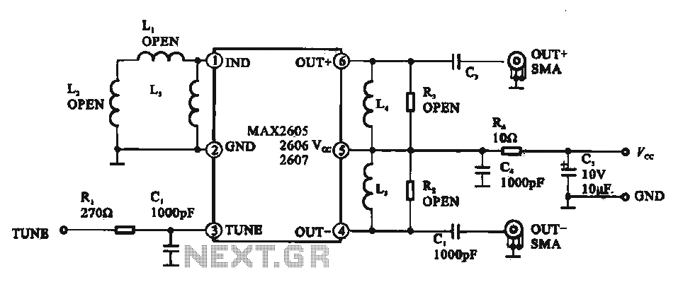
A low phase noise voltage-controlled oscillator circuit is presented, specifically integrated within the MAX2605-2609 voltage-controlled oscillator series. The circuit features a tuning voltage control terminal, allowing for adjustable oscillation frequency through a DC voltage input. The output of the...
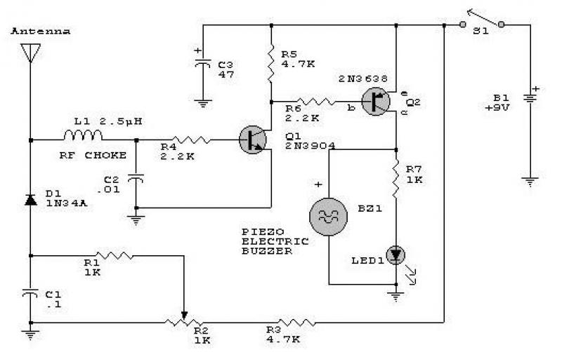
This circuit responds to RF signals below the standard broadcast band up to over 500 MHz and provides both visual and audible indications when an RF signal is detected. By adjusting the bias of diode D2 with the R2...