
5 Zone Alarm System

Zone 1 is a timed zone which must be used as the entry and exit point of the building. Zones 2-5 are immediate zones, which will trigger the alarm with no delay. Some RF immunity is provided for long wiring runs by the input capacitors, C1-C5. C7 and R14 also form a transient suppressor. The key switch acts as the Set/Unset and Reset switch. For good security, this should be the metal type with a key. At switch on, C6 will charge via R11; this acts as the exit delay and is set to around 30 seconds. This can be altered by varying either C6 or R11. Once the timing period has elapsed, LED6 will light, meaning the system is armed. LED6 may be mounted externally.
The alarm system utilizes three CMOS integrated circuits (ICs) to manage the various functions of the system effectively. The first IC handles the input processing for the zones, where each zone's normally closed contact is connected. When a switch is activated (opened), it triggers the alarm condition for immediate zones 2 to 5, while zone 1 provides a grace period for entry or exit.
The second CMOS IC manages the timing functions, particularly for the entry/exit delay. The timing capacitor C6 and resistor R11 form an RC timing circuit that dictates the delay duration. Adjustments to R11 or C6 allow for customization of the exit delay, providing flexibility based on user needs. Once the delay expires, the system transitions to armed mode, indicated by the illumination of LED6.
The third CMOS IC is responsible for the alarm sounding mechanism and the panic button functionality. When triggered, it activates the alarm sounder, providing audible notification of the breach. The panic button, when pressed, will immediately trigger the alarm regardless of the system's state, ensuring user safety in emergency situations.
The design incorporates input capacitors C1 to C5 to mitigate RF interference, which can be particularly useful in installations with long wire runs, helping to maintain system stability and reliability. The transient suppressor formed by C7 and R14 protects the circuit from voltage spikes, enhancing the longevity of the components.
Overall, this alarm system is designed with user security and convenience in mind, providing reliable monitoring of multiple zones while allowing for easy customization and installation within a residential or small office environment.This is a complete alarm system with 5 independent zones suitable for a small office or home environment. It uses just 3 CMOS IC`s and features a timed entry / exit zone, 4 immediate zones and a panic button.
There are indicators for each zone a "system armed" indicator. Each zone uses a normally closed contact. These can be micro switches or standard alarm contacts (usually reed switches). Suitable switches can be bought from alarm shops and concealed in door frames, or window ledges. Zone 1 is a timed zone which must be used as the entry and exit point of the building. Zones 2 - 5 are immediate zones, which will trigger the alarm with no delay. Some RF immunity is provided for long wiring runs by the input capacitors, C1-C5. C7 and R14 also form a transient suppresser. The key switch acts as the Set/Unset and Reset switch. For good security this should be the metal type with a key. At switch on, C6 will charge via R11, this acts as the exit delay and is set to around 30 seconds. This can be altered by varying either C6 or R11. Once the timing period has elapsed, LED6 will light, meaning the system is armed. LED6 may be mounted exter 🔗 External reference
Related Circuits
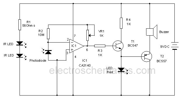
This circuit utilizes invisible infrared light to detect the movement of individuals through a doorway. A brief beep will be emitted when the infrared beam is interrupted. The infrared movement detection circuit employs an infrared LED and a photodiode or...
This circuit can be constructed using readily available low-cost components, some of which may be found in a junkbox. The specified value of 22 ohms for resistor R1 results in an average current of approximately 65 mA through the...
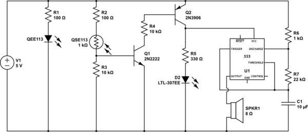
This circuit detects when a tube is empty and pulses a piezo buzzer at 5-second intervals. It is currently operational with a 5V supply on a breadboard but needs to be adapted for a 12V supply from a wall...

This circuit emits a beep and/or illuminates a LED when someone touches the door-handle from the outside. The alarm will sound until the circuit will be switched-off. The entire circuit is enclosed in a small plastic or wooden box...
This schematic is provided with the intention of being useful, but it comes without any warranty, including implied warranties of merchantability or fitness for a particular purpose. The address bus in this schematic is connected in a unique manner,...
High pressure alarm with high sensitivity. It detects high-voltage electric energy from 10kV at a distance of 2m or from low-voltage mains (AC 220V) at a distance of 0.3m. The alarm device is simple to manufacture, compact, and user-friendly....