
transistors IR Emitter/Detector with 555 timer alarm

The circuit is designed to monitor the status of a tube, activating a piezo buzzer as an alert when the tube is empty. The transition from a 5V to a 12V power supply requires careful consideration of component ratings and values to ensure proper functionality.
The piezo buzzer can be connected in series with the transistor QEE113, which acts as a switch. When the tube is detected as empty, the transistor is activated, allowing current to flow through the buzzer, producing sound at regular intervals. The choice of R1 is critical in limiting the base current to the transistor. While a 220-ohm resistor rated for 1W is the standard recommendation for 12V operation, substituting a 510-ohm, 1/4W resistor is feasible due to the short distance of 1 inch, which minimizes voltage drop and maintains adequate current flow.
To calculate the appropriate resistor values for the transistors when changing from 5V to 12V, Ohm's Law (V = IR) can be utilized. The base current can be adjusted based on the desired collector current and the transistor's current gain (hFE). For instance, if the desired collector current is 50mA, and the hFE of QEE113 is known, the base current can be calculated as follows:
1. Determine the required base current (Ib) using the formula:
Ib = Ic / hFE
2. Use Ohm's Law to find the necessary resistor value (R):
R = (V_supply - V_be) / Ib
Where V_be is typically around 0.7V for silicon transistors. This calculation will yield the resistor value required to ensure the transistor operates effectively at the new supply voltage. By applying these principles, the circuit can be optimized for the 12V power supply while maintaining its intended functionality.This circuit detects when a tube is empty and pulses a piezo buzzer in. 5 second intervals. I have it working with 5v on a breadboard, but I need to move it to 12v from a wall wart. Secondly, with 12v R1 should be 220 1W, but I want to stick with 1/4W resistors, maybe 510. Is that possible I realize that will bring down the 50ma current to QEE113 to 22mA, but my distance is only 1" so I think it will be enough power. Thridly, I`m not sure how to calculate the size of resistors needed to go to the transistors. The values I have are from various samples I found on the net for 5v. Is there a formula that tells me what they need to be for 12v. I`m not able figure that out from the datasheets. 🔗 External reference
Related Circuits
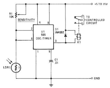
The following circuit illustrates a Photo Alarm Electronic Circuit. This circuit is based on the 555 Timer IC and incorporates features such as an LDR (light-dependent resistor). The Photo Alarm Electronic Circuit utilizes a 555 Timer IC configured in monostable...

The following circuit illustrates a Bedside Lamp Timer Circuit Diagram. This circuit is based on the CD4060 integrated circuit. Features: An LED illuminates for approximately 25 seconds. The Bedside Lamp Timer Circuit utilizes the CD4060 IC, which is a versatile...
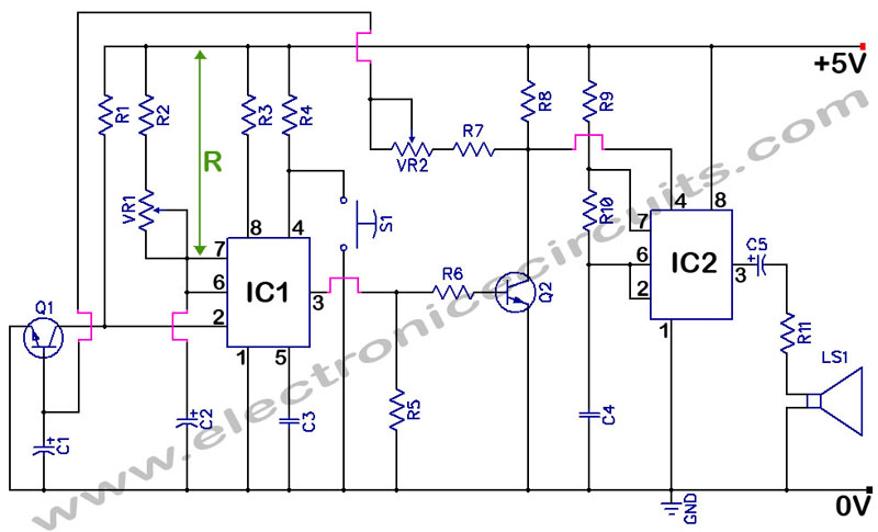
555 Timer with Audio Alarm Circuit. This circuit serves as a straightforward electronic timer equipped with an audio alarm feature. The 555 timer is a versatile integrated circuit widely used in various timer, delay, pulse generation, and oscillator applications. In...
This circuit emits a beep and/or illuminates an LED when someone touches the door handle from outside. The alarm will sound until the circuit is switched off. The described circuit functions as a touch-sensitive alarm system designed to enhance security...
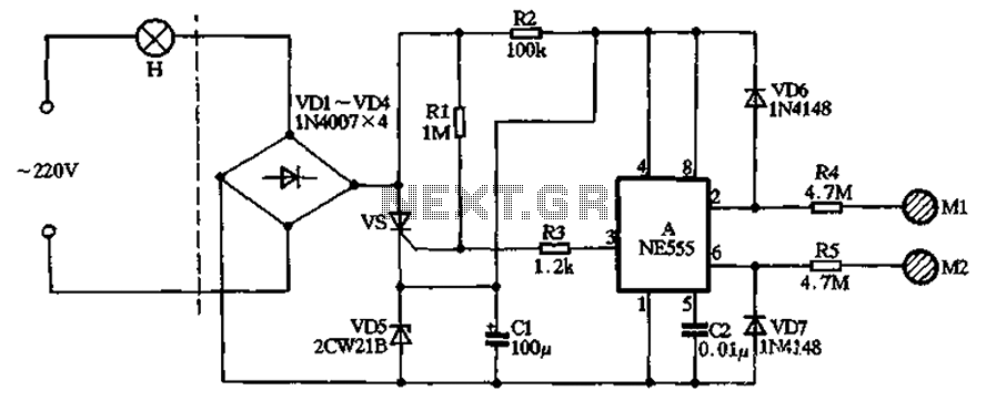
The circuit illustrated in the figure features a dashed line on the left, representing a standard lighting circuit, while the right side is responsible for the dual functionality of touch activation using the NE555 timer. Components VD1 through VD4...
This is the lowest cost dialing alarm on the market and shows what can be done with an 8-pin microcontroller. The complete circuit is shown below. You cannot see all the features of this project by looking at the...