
50 MHz converter

The described 50 MHz converter is designed to extend the coverage of general receivers, allowing for the reception of signals within the "Magic Band" frequency range of 50 MHz to 52 MHz. This frequency converter utilizes the Philips SA602 (or NE602/NE612) integrated circuit, which serves as a twice-balanced mixer oscillator. The SA602 is well-regarded for its low noise and power efficiency, making it suitable for a variety of communication applications, including VHF transceivers and RF data links.
The circuit typically consists of a few key components: the SA602 mixer, a local oscillator (LO), and a bandpass filter. The local oscillator generates a frequency that, when mixed with incoming RF signals, produces an intermediate frequency (IF) that falls within the range of the general coverage receiver. The choice of the LO frequency is critical, as it dictates the output frequency of the converter and can be adjusted to meet specific operational requirements.
In terms of performance, this converter is designed to be sensitive enough to pick up weak signals while maintaining a low noise figure, which is essential for clear signal reception, especially in crowded frequency environments. The stability of the circuit is enhanced through careful component selection and layout, ensuring that the converter can operate reliably over a range of temperatures and conditions.
The power consumption of the circuit is notably low, allowing it to be powered by standard voltage sources commonly found in portable and fixed installations. This makes it an attractive solution for hobbyists and professionals alike who require an efficient and effective means of expanding their receiver capabilities.
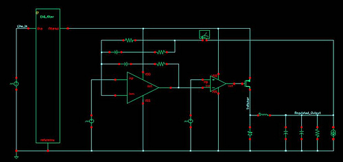
Overall, the 50 MHz converter represents a valuable addition to any general coverage receiver, enabling access to a unique segment of the radio spectrum with minimal investment in additional equipment.This is a very sensitive 50Mc converter allowing you to receive the entire "Magic Band" (50Mc...52Mc) on your general coverage receiver (28Mc...30Mc). It receives all types of modulated transmissions. It all depends on the receiver used. I`ve tested this project on a allmode Yaesu FRG-100 receiver. Within certain limits you can change the output frequency to suit your needs. The converter is very stable, low nois, sensitive and low on power consumption and can be compared to many commercial 50Mc receivers.
The heart of the converter has been built around Philips SA602 (NE602 or NE612), a twice balanced mixer oscillator. This IC finds his applications in layer capacity communication systems, cellular radio applications, RF data left, VHF-transceivers, broadb
🔗 External reference
Related Circuits
Connect with Cadence technologists and peers in the Cadence Community. Stay informed about technology trends, news, and opinions through blogs, forums, and social networking. The Cadence Community serves as a collaborative platform for professionals in the electronics design automation (EDA)...
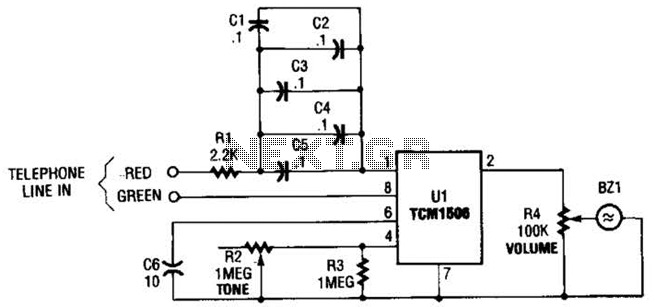
The circuit utilizes the TCM1506 ring detector/driver integrated circuit, which is a monolithic IC designed to replace mechanical bells in telephones. It is powered and activated by the telephone line's ringing signal, which ranges from 40 to 150 V...
Switch-mode power supplies are utilized in electronic circuits to efficiently increase (step up) or decrease (step down) voltage levels. In comparison to linear voltage regulators, switch-mode supplies convert minimal energy into heat, resulting in high efficiency. This characteristic is...
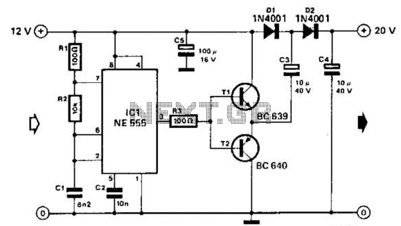
Using a 555 timer and voltage doubler, this circuit will supply over 50 mA at 20 V DC. Transistors T1 and T2 act as power amplifiers to drive the voltage doubler. The frequency of operation is approximately 8.5 kHz. The...
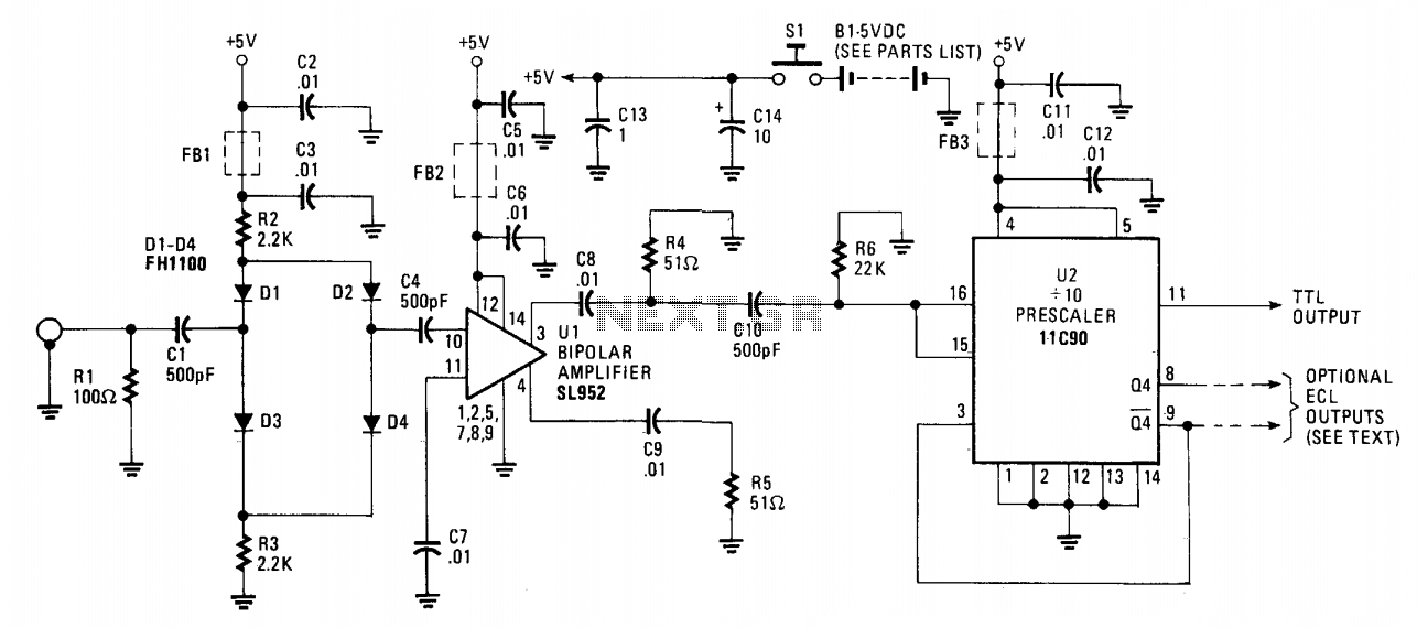
The 650 MHz prescaler probe's input is terminated by resistor R1 and is fed through C1 to the diode limiter composed of diodes D1 through D4. These diodes are forward-biased by the +5 volt supply for small input signals...
The vacuum tube remains relevant and functional in certain applications, such as in this continuous wave (CW) transmitter. The circuit is constructed in a traditional breadboard style on a wooden base. Old table radios serve as a valuable source...