
Compact Switching Step-Down Converter By MAX639

Switch-mode power supplies (SMPS) are pivotal in modern electronic circuit design due to their ability to efficiently manage voltage levels. These supplies utilize high-frequency switching techniques to regulate output voltage while minimizing energy loss. The Maxim MAX639 integrated circuit serves as an exemplary step-down converter, providing a stable +5V output from a variable input voltage between +5.5V and +11.5V. This IC is particularly advantageous in applications where space and thermal management are critical.
The design of the MAX639 allows for output voltage adjustment through a feedback network, which consists of resistors R3 and R4. By selecting appropriate values for these resistors, the output voltage can be fine-tuned to meet specific requirements. The formula R3 = R4 [(Vout / 1.28) - 1] facilitates this adjustment, enabling designers to achieve desired voltage levels with precision. The recommended value of 100k for R4 balances performance and flexibility, accommodating a range of applications.
The output current specification of 100mA ensures that the MAX639 can adequately power various loads, while the capability to substitute the Schottky diode (D1) with other compatible types allows for design flexibility. The choice of inductor L1 is also critical, as it must handle a maximum current of 500mA to prevent saturation and ensure reliable operation. This consideration is vital in maintaining the efficiency and longevity of the power supply.
In summary, the integration of the MAX639 in a switch-mode power supply design exemplifies the advantages of using specialized components in achieving efficient voltage regulation. The combination of high efficiency, adjustable output voltage, and compact design makes SMPS an essential element in contemporary electronic systems.Switch-mode power supplies are used in electronic circuits to increase (step up) or reduce (step down) voltage levels in the most efficient manner possible. Compared to linear voltage regulators, switch-mode supplies convert relatively little energy into heat.
Their efficiency is thus high. This is a major advantage with compact power supplies in particular, since it sometimes makes forced-air cooling unnecessary. Building a switch-mode supply is considerably easier if you use components that have been specially developed for this application. One example of such an integrated step-down converter is the Maxim MAX639. This is designed for axed output voltage of +5V, with an input voltage ranging between +5. 5 and +11. 5V. Although this IC is primarily designed for axed output voltage, the output voltage can be tailored using a simple feedback network.
With the given component values, resistors R3 and R4 determine the output voltage, with R3 = R4 [(Vout / 1. 28) 1] The value of R4 may lie between 10k and 10M, but a value of 100 k is a good choice for most applications.
The maximum output current is 100mA. If desired, a different type of Schottky diode with similar specifications can be used in place of D1 (a 1N5817). Inductor L1 must be suitable for a maximum current of 500mA. 🔗 External reference
Related Circuits
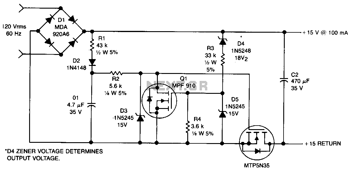
This non-isolated, unregulated converter with minimal components serves as a bridge between low-power zener regulation and the higher power applications of a 60-Hz input transformer. It is designed for scenarios where a non-isolated power supply can be utilized safely....
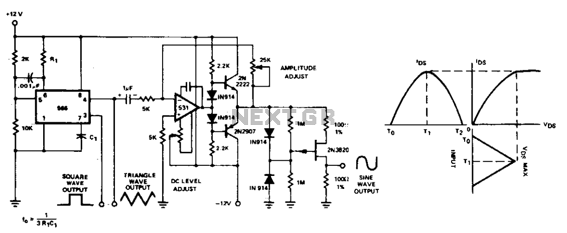
The conversion of triangle waveforms to sinusoidal waveforms is typically achieved using diode-resistor shaping networks, which effectively reconstruct the sine wave segment by segment. Two simpler and more cost-effective methods can be employed to shape the triangle waveform of...
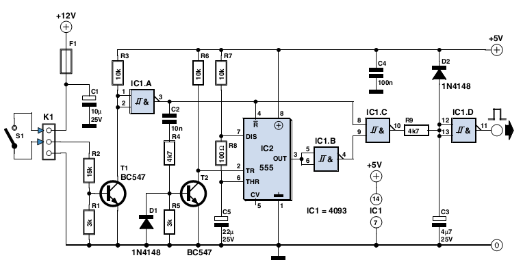
The circuit described here was designed as an addition to a remotely controlled garage door opener. The problem was that a brief burst of interference, arising from a thunderstorm or a mains spike, was enough to trigger the mechanism,...
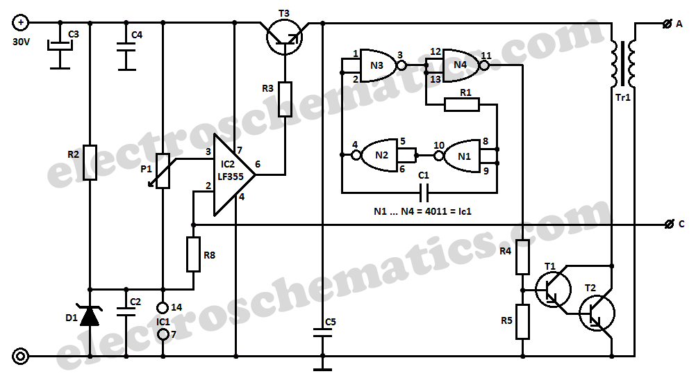
This DIY 12V to 220V DC to AC converter utilizes a CMOS 4047 as its main component, effectively transforming 12V DC into 220V AC. The circuit design of this DC to AC converter primarily revolves around the CMOS 4047 integrated...
This project originated from an interest in a new form of radio transmission known as Digital Radio Mondiale (DRM), which is a digital shortwave transmission method. While there are a few devices available from Europe for decoding these digital...
High-efficiency step-down switching regulators for positive voltages are common; however, negative step-down switching regulators (negative voltage in, negative voltage out, common ground) are less well known, despite their frequent necessity. Setting them up is not particularly challenging, but literature...