
50 to 150MHz high frequency VCO circuit

The Bong circuit operates as a high-frequency oscillator based on the Colpitts configuration, which is characterized by its use of capacitive feedback to achieve sustained oscillation. The primary component, a Ge coil (inductor), is essential for determining the oscillation frequency alongside the capacitors in the circuit. The inclusion of a varactor diode allows for dynamic tuning of the resonant frequency, making the oscillator versatile for various applications, particularly in RF circuits.
The circuit's architecture includes two heads, which may refer to dual output stages or separate sections for different functionalities. The simplicity in production implies that the circuit can be easily assembled with commonly available components, making it suitable for educational purposes or prototyping.
The output amplifier (Trz) is critical in ensuring that the oscillation signal maintains integrity and strength. Additionally, it serves a dual purpose by acting as a buffer, isolating the output from the preceding stages and preventing loading effects that could alter the performance of the oscillator. The mutual impedance converter transformer (Tt-1) enhances signal transfer between stages, ensuring that the oscillation is not adversely affected by impedance mismatches.
The design also incorporates an annular enameled iron core (L2) with a specific winding configuration (double 10 turns). This choice of core material and winding technique is aimed at optimizing inductance and minimizing losses, thereby enhancing the overall efficiency of the circuit. The careful selection of these components and their arrangement is crucial for achieving the desired high-frequency performance and stability in oscillation. Bong circuit is a high frequency Colpitts circuit l shake Ge coil L, there are two f head, simple production, by determining the frequency of oscillation and tested to determin e the value of the port Lt varactor diode directly change the resonant frequency, so vco work, the oscillation signal output can be extremely t If the output from the output amplifier Trz doubles as a buffer from Tt-1 shot from the mutual impedance converter transformer role, L 2 by the annular fP0.4 enameled iron core wound double 10 laps from.
Related Circuits
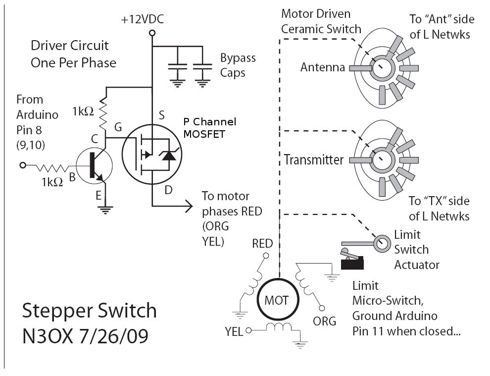
Information is needed regarding a circuit to manage the Remote Coax Ameritron RCS-10, as no diagram can be found on Google. The Ameritron RCS-10 is a remote coax switch designed for amateur radio applications, allowing users to control multiple antennas...
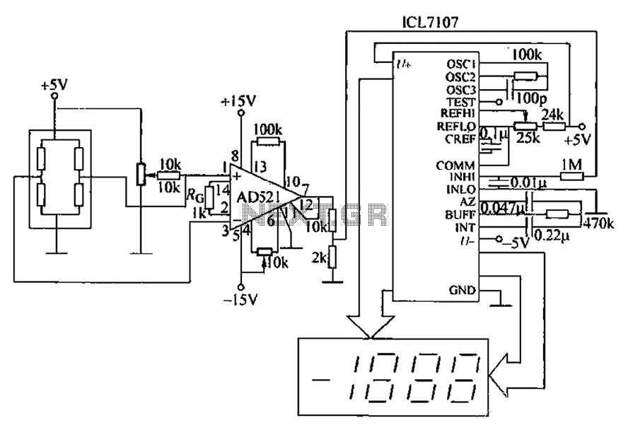
A pressure sensor circuit features a pressure sensor with a nominal resistance of 120 ohms. The amplifier circuit utilizes an AD521 operational amplifier with a gain of 100. It includes resistor components Rs and Rc, along with a decision-making...
This circuit is an adjustable voltage reference circuit, which serves as a voltage source that provides a voltage greater than that of the reference diode. High precision applications that operate over an extended temperature range necessitate a restriction on...
This cable TV amplifier circuit is an RF amplifier designed for quick installation between two coaxial cables. Both the input and output impedances are compatible with 75-ohm cables. The main amplifier is the T1 transistor, while T2 functions as...
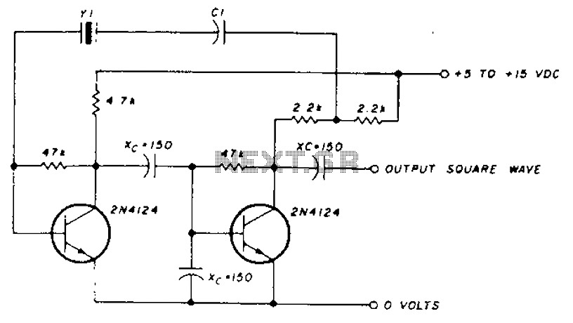
A transistor in series with capacitor C1 can be utilized to adjust the oscillator output frequency. The frequency may vary with changes in capacitance ranging from 20 pF to 0.01 µF, or as determined by the tuning capacitor. The...
This circuit is straightforward. The initial 555 timer prevents the second timer from being activated while the first is operational. Drive the circuit with a simple 12-volt power supply. The circuit utilizes two 555 timer integrated circuits (ICs) configured in...