
Simple Cable TV Amplifier Circuit

The cable TV amplifier circuit is engineered to enhance the signal strength of RF signals transmitted through coaxial cables. The design includes two primary components: the T1 transistor, which serves as the main amplification element, and the T2 transistor, configured as an emitter follower to provide impedance matching and improved linearity. The input and output stages are designed to maintain a 75-ohm impedance, which is crucial for minimizing signal reflection and ensuring optimal performance in cable television applications.
Resistors R3 and R4 play a vital role in establishing the feedback bias for the T1 transistor, allowing for stable operation and consistent gain across the specified frequency range. The circuit is optimized for frequencies up to 150 MHz, making it suitable for standard cable TV signals. It is important to note that while the transistors can theoretically operate up to 2 GHz, practical performance is limited to lower frequencies due to factors such as parasitic capacitance and the inherent characteristics of the components used.
Housing the circuit in a metal case is essential for shielding against electromagnetic interference (EMI), which can degrade signal quality. The choice of 75-ohm coaxial cables is also critical, as using mismatched impedance can lead to signal loss and distortion. The overall current consumption of approximately 20 mA indicates a low-power design, making it efficient for continuous operation in residential or commercial settings.
In summary, this cable TV amplifier circuit is a robust and efficient solution for boosting RF signals in coaxial cable systems, with careful attention given to component selection, impedance matching, and shielding to ensure high performance and reliability in signal transmission.This cable tv amplifier circuit is a rf amplifier designed to be quickly installed between two coaxial cables. Both input and output impedances are compatible with 75 © cables. The main amplifier si T1 transistor, T2 is working as an emitter follower. The feedback bias is determined by R3 and R4. Because of the high frequency limit of transistors (<= 2GHz) the tv amplifier works well up to 150 MHz. It must be housed in a metal case and the coaxial cables must de 75 © type. The total current consumption of this tv cable amplifier circuit is around 20mA. 🔗 External reference
Related Circuits
This clock timer utilizes a PIC16F628 microcontroller to display a 3.5-digit time format and control an external load. It is programmable to time intervals from 1 to 59 minutes. The clock features a calendar that accounts for leap years...
This circuit includes a 2048 radio remote control transmitter and a corresponding wireless receiver that features high reception sensitivity and low power consumption. The combination of these two components provides a highly reliable remote control system, suitable for various...
This project involved the design of an audio amplifier capable of delivering substantial output power with minimal component count while maintaining high quality. The power amplifier section utilizes three transistors along with a few resistors and capacitors in a...
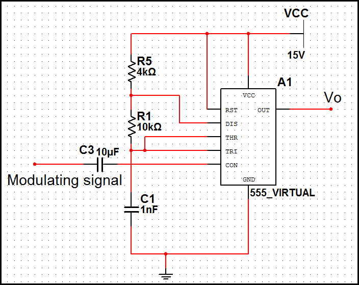
In pulse position modulation, the amplitude and width of the pulses are kept constant, while the position of each pulse with reference to the position of the reference pulse is changed according to the instantaneous sampled value of the...
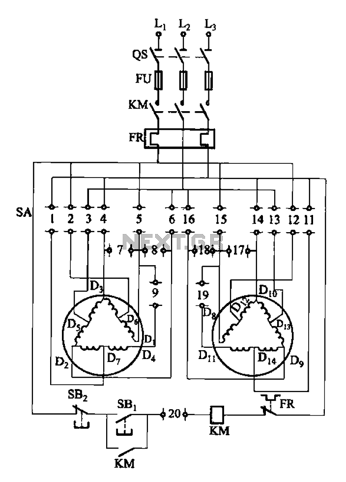
The 3-119 circuit shown in the figure combines switch SA to realize the stator windings, specifically the 2, Y, and 2Y connections, which correspond to the motor speed n1. The 3-119 circuit is designed to facilitate the control of motor...
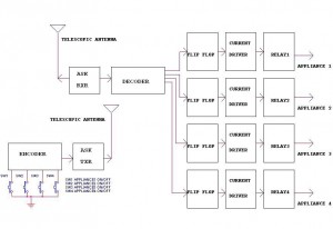
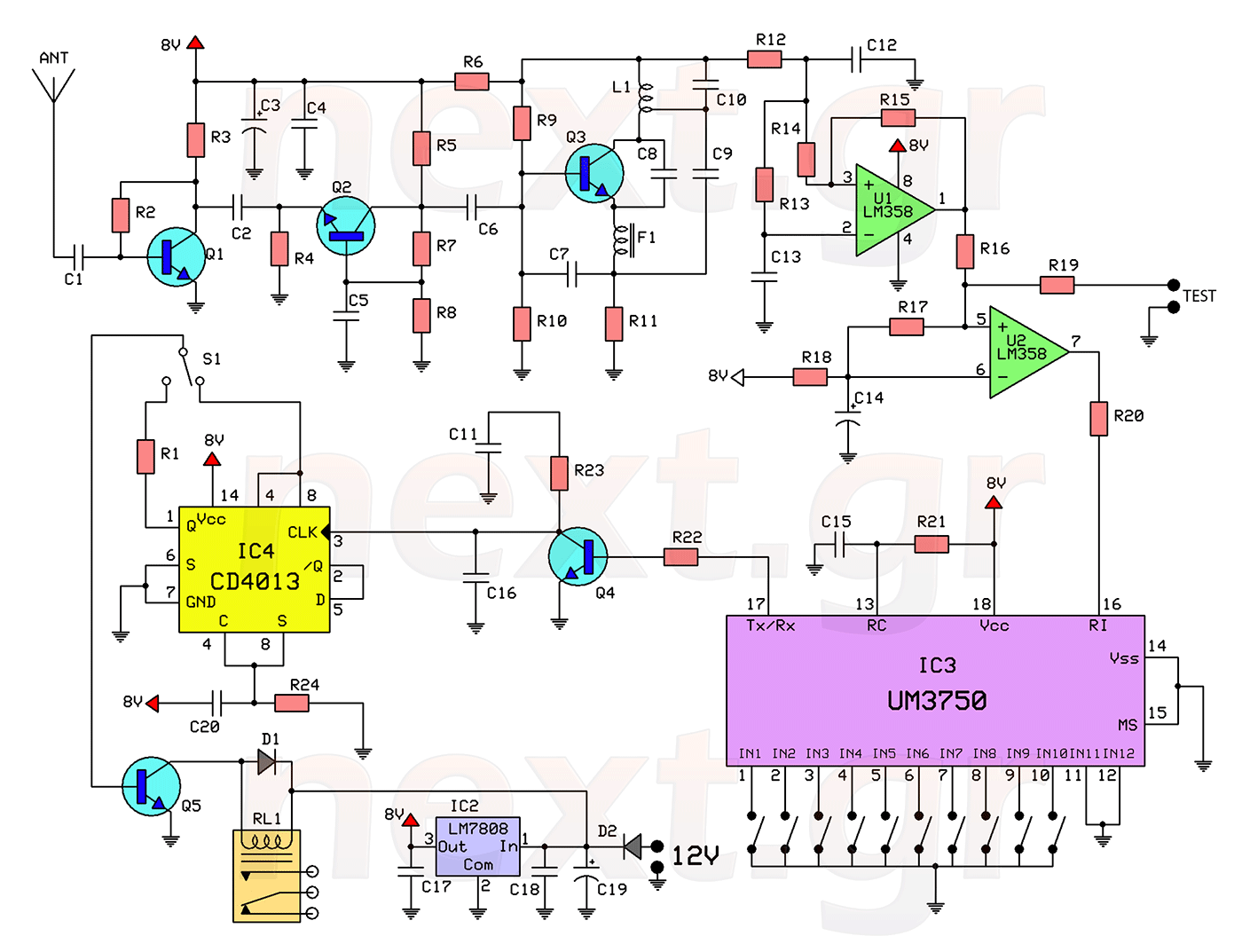
This circuit illustrates a remote control circuit diagram using RF technology without the use of a microcontroller. Features include a simple remote control circuit that operates via radio frequency. The remote control circuit operates by transmitting signals through radio waves,...