
500 watt inverter 12vdc to 220vac

The inverter circuit described involves a transformer that plays a crucial role in converting low voltage DC to high voltage AC. The transformer is specified with a center-tapped secondary rated at 12V, allowing for flexibility in output configurations. The primary winding is designed to handle voltages up to 220V, making it suitable for various applications that require high voltage output.
The flip-flop, which is a key component in this circuit, is responsible for generating the necessary square wave signal at a frequency of 50 Hz. This frequency is standard for many AC applications, especially in regions where the electrical grid operates at 50 Hz. The flip-flop can be implemented using various logic ICs or discrete components, depending on the design requirements and available resources.
In operation, the circuit begins with a DC voltage input, which is fed into the inverter. The flip-flop generates a square wave that drives the primary winding of the transformer. As the current flows through the primary, it induces a magnetic field in the transformer core, which in turn induces a higher voltage in the secondary winding due to the principles of electromagnetic induction. The center-tap configuration allows for either a 12V output or a split output that can be utilized in different applications.
This inverter circuit is commonly used in applications requiring isolated power supplies, such as in off-grid solar systems, uninterruptible power supplies (UPS), and various electronic devices that require a stable AC output from a DC source. Proper design considerations must be taken into account, including the selection of appropriate components to handle the expected load, thermal management, and safety measures to ensure reliable operation.Step up part of this inverter circuit using a transformer 12VCT/500VA in secondary and primary 0 - 220V. While the frequency is determined by the flip-flop which is set to 50 Hz. 🔗 External reference
Related Circuits
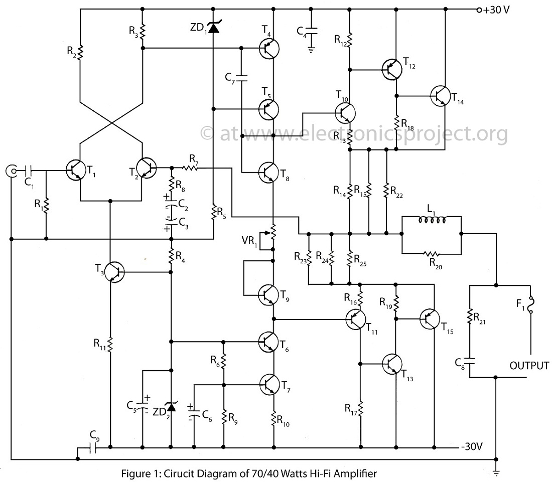
The 70/40 Watts Hi-Fi amplifier is an advanced and high-quality audio amplifier that features an almost 0% distortion circuit design. This amplifier is renowned for its exceptional sound quality and performance. The 70/40 Watts Hi-Fi amplifier utilizes a sophisticated circuit...
The objective is to transmit additional information through the distribution of articles. Please contact us via email at [email protected] within 15 days if there are any issues related to article content, copyright, or other concerns. Prompt action will be...
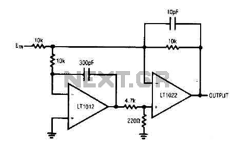
The circuit comprises a low drift LT1012 device and a high-speed amplifier LT1022. It functions as a unity gain inverter, with the summing node located at the junction of three 10k ohm resistors. The circuit monitors the summing node...
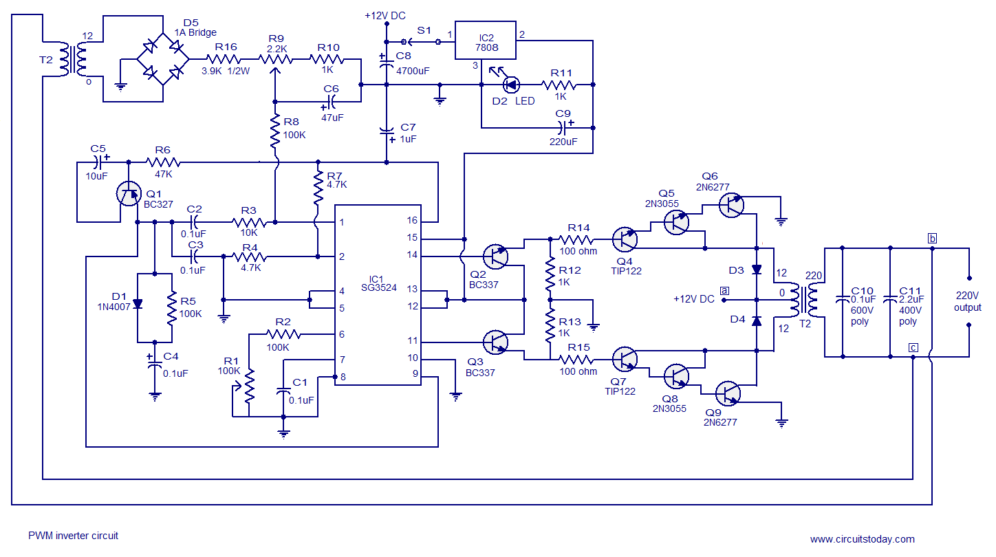
A simple PWM inverter circuit utilizes the SG3524 integrated circuit. This PWM inverter is designed for a 12V input, providing a 220V output with a maximum output power of 250 watts. The output power can be extended further. The described...
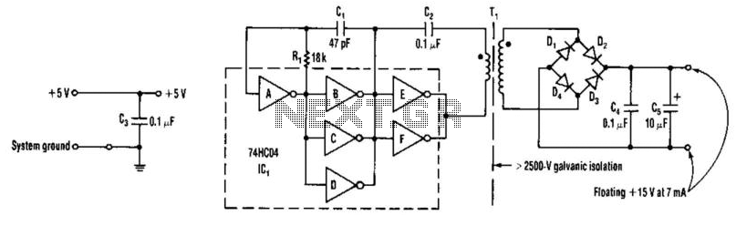
A DC-DC converter utilizes a 74HC04 to drive transformer Tl. Tl is a ferrite-core transformer from Fair-Rite, Inc., with part number 597-5000201, featuring a 7-turn primary winding and a 25-turn secondary winding. Kynar #30 wire wrap wire is employed...
While I would have liked a 4 channel chip with about 20 Watt per channel, the local parts store didn't have any yet, so I opted for two TA8215AH stereo chips, selected by their low price in this particular...