
500mW FM transmitter

The TX500 FM transmitter circuit is designed to operate efficiently within the FM broadcast band, allowing for audio transmission with a maximum output power of 500mW. The circuit is modular, comprising three main functional blocks: the modulator/oscillator, a dual-stage VHF amplifier, and an LED-based power meter, which provides visual feedback on the output power level.
The modulator/oscillator block generates the carrier frequency, which is crucial for FM transmission. The frequency is adjustable and can be set between 88 MHz and 108 MHz, making it compatible with standard FM radio receivers. The tuning of the oscillator is achieved through the combination of capacitors C4 and C5 and the inductance of the coil L1. Specifically, the oscillator requires 3.5 turns of wire for L1, with a capacitance of 27pF for C5 to effectively tune the circuit to the lower part of the FM band (88-100 MHz). This tunability is essential for compliance with local broadcasting regulations and to avoid interference with existing FM stations.
The VHF amplifier consists of two amplification stages, which increase the output power to the desired level while maintaining signal integrity. This design ensures that the transmitted signal is strong enough to be received clearly over a reasonable distance without significant distortion. The amplifier stages are carefully designed to operate with minimal power consumption, drawing less than 100mA, which allows for the use of portable power sources such as a 9-12V battery.
Lastly, the LED-based power meter provides a convenient method for users to monitor the transmitter's output power in real-time. This feature is particularly useful for ensuring the transmitter operates within safe limits and for making adjustments as necessary.
Overall, the TX500 is a well-structured FM transmitter that balances performance with ease of construction, making it suitable for hobbyists and educational purposes alike. Its modular design enhances understanding of radio frequency circuits by allowing users to study each component's function independently.The TX500 is a simple to build 500mW FM Transmitter. It consists of three blocks; modulator / oscillator, two stage 500mW VHF amplifier and LED based power meter. The TX500 allows to transmit audio signals to FM band at frequencies from 88 MHz to 108 MHz. Due to the very low power consumption of less than 100mA the circuit may be perfectly powered by using 9-12V battery or power supply if you prefer.
The circuit has been divided into separate stages so that it is be better for everyone to understand how every part works independently. The carrier frequency of an oscillator is determined by the capacity of C4, C5 in conjunction with the inductance of the coil L1. 3.5 turns are needed and 27pF for C5 to tune to a lower part of FM band (88-100MHz). To be able to tune to a higher part (100 🔗 External reference
Related Circuits
This circuit utilizes a ceramic tuning resonator with a frequency of 3.587 MHz, alongside resonator filters available at frequencies of 5.5 MHz, 7.7 MHz, and 10.7 MHz. The transmission range of the device is approximately 2-4 km. The circuit...
FM Broadcast Audio Transmitter. The circuit includes a frequency-modulated oscillator, an audio preamplifier with pre-emphasis to provide the frequency-modulating signal, and a buffer amplifier to drive the antenna connector. The FM radio pirate introduction to community radio electronics presents...
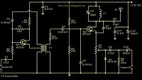
The TV transmitter described utilizes UK standard 1 FM modulation for sound and PAL modulation for video. The audio signal to be modulated is first amplified using transistor Q1 and its associated components. Transistor Q2 serves dual functions: generating...
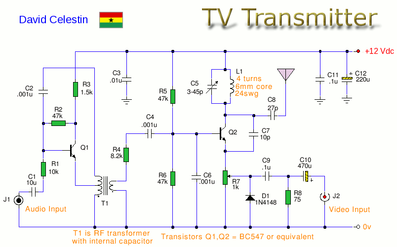
This is an analogue TV transmitter. Sound modulation is FM with a 5.5 MHz carrier, and video transmission uses PAL. The frequency is adjustable via C5 and tunes from 54 to 216 MHz with the components shown. This transmitter...
The 2N2222 circuitry is a three-element phase-shift oscillator circuit designed to produce a 1,000 Hz sine wave. This sine wave is subsequently applied to the TCG-610 varactor diode, which has a capacitance of 6 pF at 4 V. The...
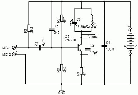
This is a simple FM transmitter circuit utilizing a medium power 2N2218 transistor. An electret type microphone is connected to two input terminals, and the antenna should be a copper wire measuring between 15 to 40 cm. Below is...