
FM Transmitter with 2N2218

The FM transmitter circuit operates by converting audio signals from the electret microphone into radio frequency signals. The 2N2218 transistor serves as the main amplification element in this circuit. The electret microphone picks up sound waves and converts them into electrical signals, which are then fed into the base of the transistor.
The circuit typically consists of a few key components: the electret microphone, the 2N2218 transistor, resistors, capacitors, and the antenna. The microphone is powered by a biasing resistor connected to a suitable voltage source, often a battery. The output from the microphone is coupled to the base of the transistor through a coupling capacitor, allowing only the AC audio signals to pass while blocking any DC components.
The transistor amplifies the audio signal, which is then modulated onto a carrier frequency. This modulation process allows the audio signal to be transmitted over radio waves. The output from the collector of the transistor is connected to the antenna, which radiates the modulated signal into the surrounding environment.
The length of the antenna plays a crucial role in determining the transmission range and quality of the signal. A copper wire antenna between 15 to 40 cm is typically used, as it is well-suited for the frequency range of the FM band. The choice of length can be adjusted based on the desired frequency of operation, with shorter lengths generally favoring higher frequencies.
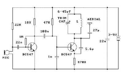
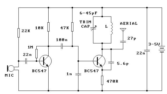
Additional components may include capacitors for frequency stabilization and resistors for setting the biasing levels of the transistor. The overall design of the circuit is straightforward, making it suitable for hobbyists and educational purposes in understanding basic radio frequency transmission principles. Proper layout and component selection are essential to achieve optimal performance and minimize interference in the transmitted signal.Here`s simple FM transmitter circuit using medium power 2N2218 transistor. Micropohone is of electret type that connects to two input terminals and the antenna should be a copper wire from 15 to 40 cm. Below is schematic circuit of the fm transmitter.. 🔗 External reference
Related Circuits
Place the transmitter approximately 10 feet away from an FM radio. Set the radio to a frequency between 89 and 90 MHz. Walk back to the FM transmitter and turn it on. Separate the windings of the coil by...
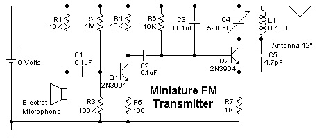
Construct a simple mini FM transmitter. This engaging project demonstrates how to create a mini broadcasting transmitter capable of transmitting an audio signal up to a quarter mile to any FM receiver. It is straightforward to assemble and offers...
The circuit of the transmitter is shown in Figure 1, and as you can see it is quite simple. The first stage is the oscillator, and is tuned with the variable capacitor. Select an unused frequency, and carefully adjust...
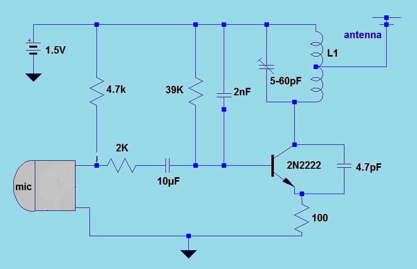
This simple FM (frequency modulation) transmitter is powered by a 1.5V battery and utilizes a single frequency determined by the transmitter transistor. It is controlled by an LC resonant circuit and operates within a frequency range of 80 to...
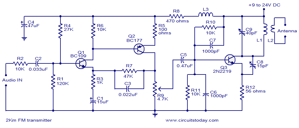
With a matching antenna, the FM transmitter circuit can transmit signals over a range of 2 kilometers. The transistors Q1 and Q2 form a highly sensitive preamplifier stage. The audio signal to be transmitted is coupled to the base...
This FM transmitter circuit is very simple and has acceptable transmission. The signal transmitted from this FM transmitter circuit can be received at almost 300 meters in open air. The circuit requires a 3-volt operating voltage and can be...