
500w hf linear amplifier circuit diagram wiring

The 150-watt amplifier circuit is designed to provide high power output while maintaining cost efficiency, making it suitable for various audio applications. The core components of this circuit are the Darlington power transistors, TIP142 and TIP147, which are known for their high current gain and ability to handle significant power levels.
The schematic typically includes input and output stages, biasing networks, and feedback loops to ensure stability and linear amplification. The input stage may consist of a differential amplifier configuration to improve signal integrity and reduce noise. The use of Darlington pairs enhances the current-driving capability, allowing the amplifier to deliver substantial output power to speakers or other loads.
Power supply considerations are crucial for the amplifier's performance. A suitable power supply must be selected to provide adequate voltage and current levels to the transistors. Capacitors may be included in the design to filter power supply noise and ensure stable operation.
Thermal management is also a key aspect of the circuit design. Heatsinks should be employed with the power transistors to dissipate heat effectively, preventing thermal runaway and ensuring reliability during extended operation. Additional protection circuits, such as fuses or thermal cutoff switches, may be integrated to safeguard the amplifier from overload conditions.
Overall, this 150-watt amplifier circuit represents an effective solution for those seeking a powerful yet economical audio amplification system. The use of TIP142 and TIP147 transistors highlights its capability to deliver high performance in various applications.This is a low cost 150 watt amplifier circuit with diagram and schematic design using two darlington power transistors tip 142 and tip 147. this amplifier circuit can This is a low cost 150 Watt amplifier circuit with diagram and schematic design using two Darlington power transistors TIP142 and TIP 147.
This amplifier circuit can. 🔗 External reference
Related Circuits
This house FM transmitter for your stereo or any other amplifier provides a strong signal strength up to a distance of 500 meters with a power output of about. This FM transmitter is designed to enhance audio transmission capabilities for...

The following circuit is a power amplifier circuit for an FM transmitter with an output power of 30 watts. The power amplifier circuit utilizes a power transistor of type 2SC1946A. The FM transmitter operates with a 13.8-volt DC power...

This temperature meter utilizes the precision micro power centigrade sensor IC LM35. The output voltage of the IC is linearly proportional to 10 mV per degree centigrade. The LM35 temperature sensor is a versatile and widely used device in electronic...
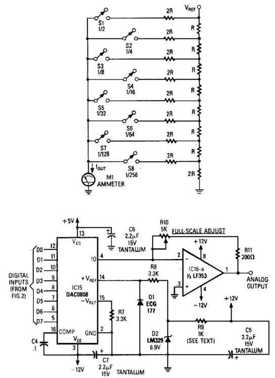
Figure A illustrates an R/2R resistor ladder. Each closed switch increases the current output. A basic channel A/D converter is depicted in Figure B. The voltage reference (D2) is shared among all channels, while the value of the dropping...
This is a simple automatic light switch circuit designed for bedrooms. After construction, the input terminals of this circuit should be connected in parallel to the intended lighting fixture. The automatic light switch circuit utilizes a light-dependent resistor (LDR) as...
This paper describes an RF amplifier circuit which is suitable for the frequencies between 10MHz and 500MHz. These kind of amplifiers are called wide band amplifiers. Wide band amplifiers are used in communication receivers, RF measuring equipment and tons...