
Clock Alarm Light Switch Circuit

The automatic light switch circuit utilizes a light-dependent resistor (LDR) as the primary sensing element, which detects ambient light levels. When the light intensity falls below a certain threshold, the LDR decreases its resistance, triggering a transistor switch that activates a relay. This relay can then control the power supply to the light fixture, turning it on automatically in low-light conditions.
The circuit typically includes a power supply, which can be derived from standard AC mains or a low-voltage DC source, depending on the design requirements. The LDR is connected in a voltage divider configuration with a fixed resistor, creating a reference voltage that is fed into the base of a transistor. When the ambient light dims, the voltage across the LDR drops, allowing the transistor to turn on, energizing the relay coil.
Additional components may include diodes for flyback protection across the relay coil, ensuring that voltage spikes generated during relay deactivation do not damage the transistor. Capacitors may also be incorporated to filter noise and stabilize the circuit operation.
This circuit is ideal for applications in bedrooms, hallways, or any area where automatic lighting is beneficial, enhancing convenience and energy efficiency. Proper consideration should be given to component ratings and specifications to ensure reliable operation within the intended environment.Here is an ultra simple automatic light switch circuit for bedrooms. After construction, connect the input terminals of this circuit in parallel to the int.. 🔗 External reference
Related Circuits
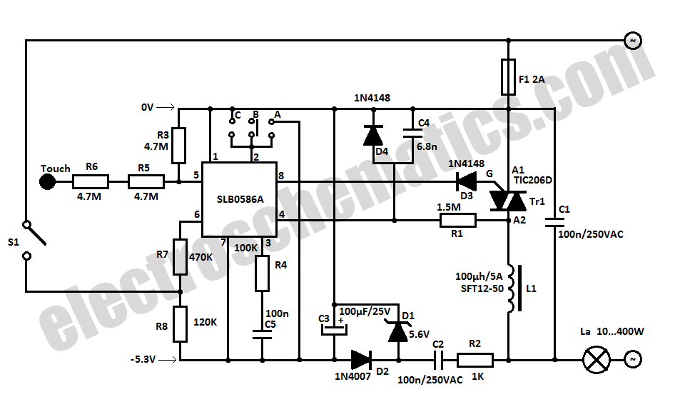
The SLB0586A integrated circuit from Siemens can be utilized to create a simple touch light dimmer circuit, allowing for the adjustment of lamp intensity. When paired with a TIC206D triac, this setup enables smooth regulation of light intensity for...
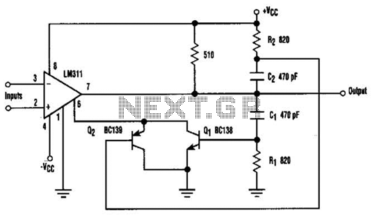
When the comparator's output transitions from low to high, the rising edge of the output pulse, differentiated by the Cl/Rl chain, activates Ql. This action blocks the comparator via its strobing input and maintains its output state for a...
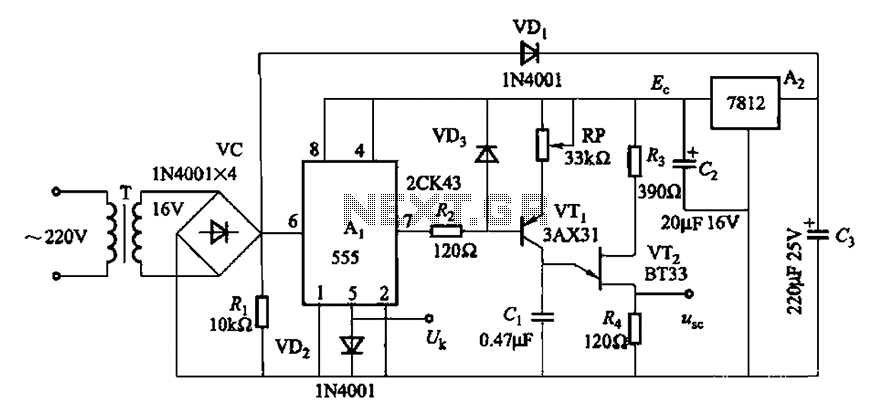
Both circuits can synchronize trapezoidal wave voltage, which is converted into intermittent small rectangular pulses. Its working principle involves periodic operation in synchronization with the grid frequency of the zero-volt switching voltage of the DC chopper. Due to the...
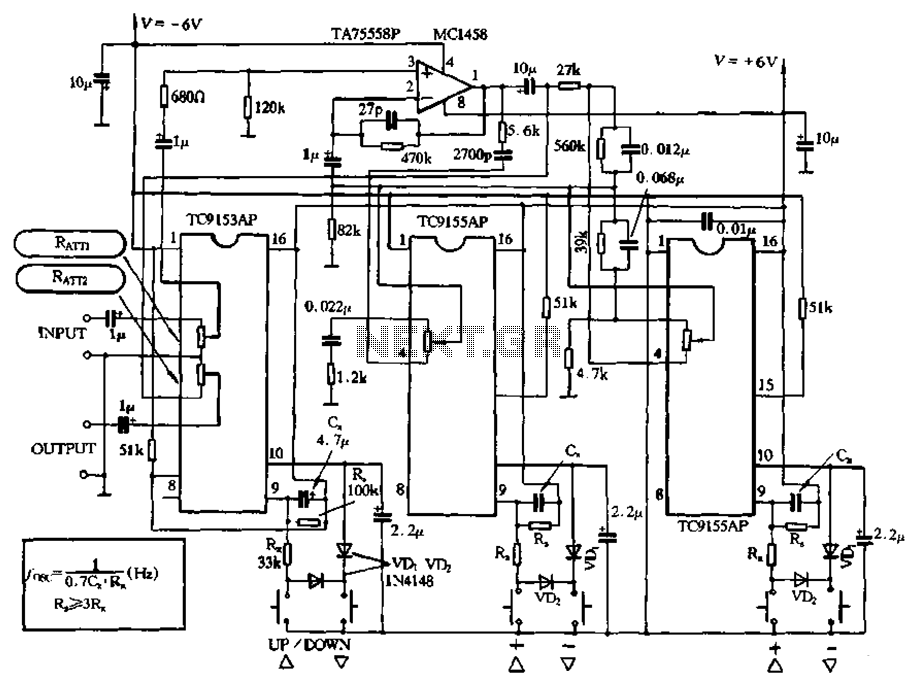
Figure 4-18 illustrates a volume potentiometer T (Xi 153AP) and a tone potentiometer T (155AP) that make up a volume and tone control circuit. This circuit includes Rx and Cx as clock oscillation elements, with values selectable based on...

A basic LED driver circuit consists of a 5-volt power source, a 2 kΩ potentiometer, and an LED. The LED is forward biased, with the manufacturer specifying a maximum current rating of 20 mA at a diode voltage drop...
This power supply was designed for use with the Simple hybrid amplifier published elsewhere in this issue. It is suitable for various applications as well. A cascade generator is utilized for the 170 V output, a switch-mode supply provides...