
500W power inverter circuit diagram

The 500W power inverter circuit utilizes the 2N3055 transistors, which are known for their high current handling capabilities, making them suitable for power amplification in this application. The multivibrator, which serves as the frequency generator, can be implemented using a pair of transistors configured in a feedback loop to produce a square wave output. This square wave is then transformed into a sine wave using an LC filter or transformer, depending on the design requirements.
In the case of the 100W inverter circuit, the use of the CD4047 integrated circuit allows for precise frequency control and stability, generating a sine wave output that is then amplified by the 2N3055 transistors. The circuit's efficiency is critical, and the design aims to minimize losses in the power conversion process, ensuring that the output voltage remains stable under varying load conditions.
The 250W inverter circuit demonstrates versatility in output voltage based on transformer selection, thus allowing for adaptability in various applications. The inclusion of a timer IC 555 for generating a 120Hz signal is an efficient way to control the switching of the transistors, providing a reliable operation for the inverter system.
Overall, these inverter designs showcase practical applications of transistor-based circuits for power conversion, highlighting the importance of component selection, circuit topology, and efficiency in achieving desired performance levels.This is the scheme diagram of 500W power inverter circuit which build using 10 pieces of well-known NPN power transistor 2N3055 to amplify the AC signal produced by multivibrator. The frequency generator / multivibrator is built based on transistors too. All of the components is easy to gathered from the. This is the 500W power inverter circuit, converting a 12VDC battery (usually car battery) to become 220-240V AC power. The inverter is powered using 6 pairs of transistor TIP35C which connected in parallel, so it will be 12 TIP35C transistors. There is certainly only one variable resistance in this circuit. This is the circuit diagram of inverter for 8W fluorescent lamp. The circuit is build based ZTX652 transistor, and used to drive an 8W fluorescent lamp from a 12V source.
The inverter will work from 10V to 16. 5V DC supply, attaining efficiencies up to 78% thus making it suitable for. Here the schematic diagram of 100W Inverter Circuit which will convert 12VDC input to be 220VAC output. The circuit built based IC CD4047 to generate sine wave signal 50Hz and then the power transistor 2N3055 will boost the signal so that the signal have high power (high electric current).
Then. This 250W inverter circuit converts the 12V DC input from car battery. The output will be 120V AC or 220V AC depended on the transformer used. The inverter work at 60Hz frequency. The inverter circuit operation is very simple. The IC1 (timer IC 555) will generate a 120-Hz signal. Then. We aim to transmit more information by carrying articles. Please send us an E-mail to wanghuali@hqew. net within 15 days if we are involved in the problems of article content, copyright or other problems. We will delete it soon. 🔗 External reference
Related Circuits
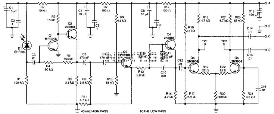
This receiver is designed to detect infrared (IR) or light beams that are frequency modulated on a 50-kHz carrier. The transistors Q2, Q1, Q3, and Q4 form an active filter and amplifier, while the differential amplifier formed by Q5...
This amplifier circuit integrates the LT1010 with a fast discrete stage and employs an LT1008-based DC stabilization loop. It features a differential stage that operates in a single-ended configuration. The described amplifier circuit is designed to enhance signal amplification while...
1997 Toyota Camry Fuel Pump Wiring Diagram. The fuel pump wiring diagram for the 1997 Toyota Camry provides a detailed representation of the electrical connections associated with the vehicle's fuel pump system. This diagram typically includes the power supply lines,...
Hello everyone, please examine this circuit. I constructed it recently, but it is not functioning. I have verified all connections and components, and everything appears to be in order. However, when I power it on... The circuit in question appears...
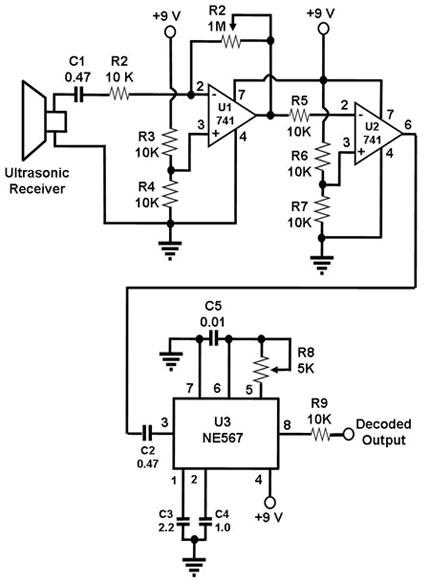
The ultrasonic receiver utilized in this circuit is specifically designed to vibrate optimally at a frequency of approximately 40 kHz. Consequently, the transmitter associated with this receiver must also emit waves at 40 kHz. When these waves interact with...
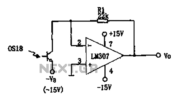
The circuit described is a photoelectric receiver amplifier designed to amplify the electrical signals generated by photodiodes or phototransistors in optoelectronic devices. When the intensity of incident light varies, the photosensitive device generates a corresponding voltage or current. The...