
Fm Light Beam Receiver Circuit

The described receiver circuit utilizes a combination of active components to effectively process modulated signals. The initial stage consists of transistors Q2, Q1, Q3, and Q4, which are configured as an active filter and amplifier. This configuration is essential for filtering out unwanted noise and amplifying the desired signal. The choice of a 50-kHz carrier frequency allows for efficient modulation and demodulation of the IR or light signals, making it suitable for various applications, such as remote controls or wireless data transmission.
Following the active filter stage, the differential amplifier formed by transistors Q5 and Q6 plays a crucial role in further enhancing the signal. Differential amplifiers are known for their ability to reject common-mode noise, which is particularly beneficial in environments with significant electromagnetic interference. By amplifying the difference between the two input signals, Q5 and Q6 ensure that the output maintains the integrity of the modulated information while increasing the overall gain of the circuit.
In summary, this receiver circuit is adept at capturing and processing frequency-modulated light signals, utilizing a well-structured combination of active filtering and differential amplification to achieve high fidelity and noise resilience in the output. The design is tailored to optimize performance for applications requiring reliable signal detection in the presence of potential noise sources. This receiver will pick lip IR or light beams that are frequency modulated on a 50-kHz carrier. Q2/Q1/Q3/Q4 from an active filter and amplifier and differential amp Q5/Q6 provide more gain.
Related Circuits
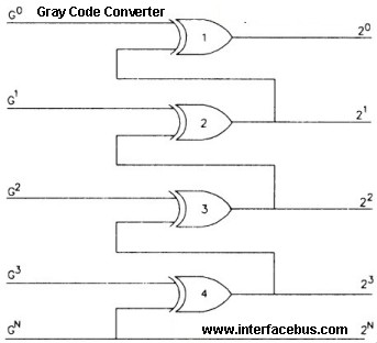
Gray Code is a positional binary number notation where any two numbers differing by one are represented by expressions that are identical except in one position, differing by only a single unit in that place. This code consists of...
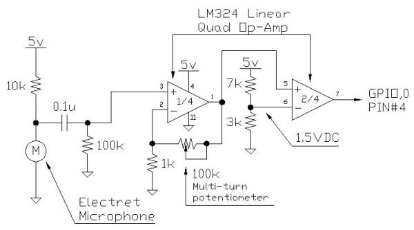
Instructions for creating a Clap-Clap On/Clap-Clap Off switch circuit. This guide provides the necessary information for constructing a clap-activated switch. The Clap-Clap switch circuit is an innovative design that utilizes sound activation to control electronic devices. The primary components of...

User Agreement & Disclaimer Disclaimer: All files are found using legitimate search engine techniques. This site does not condone hacking into sites to create the links it lists. It is assumed that all links found on the search...
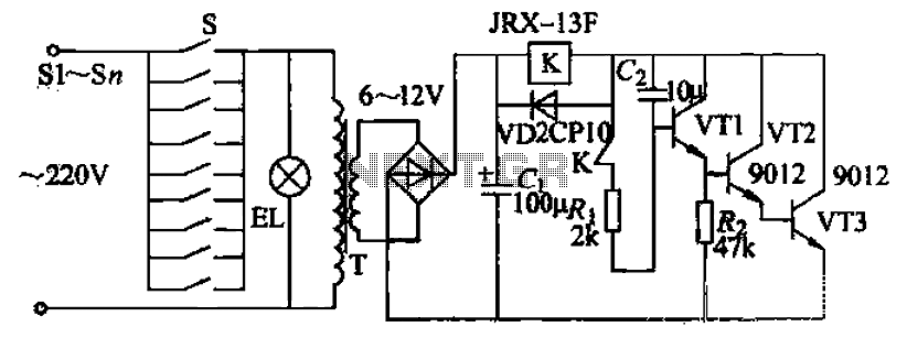
Pressing the button switch Sl-Sn activates the circuit, turning on the transformer T. The low-voltage alternating current from the secondary winding is directed to a bridge rectifier and a filter capacitor Ci, which produces a DC voltage. This voltage...

Binu submitted a new resource: Circuit and Program to Interface MT8870 with AT89S51 (version 1.0) - Decoding the DTMF signals from the telephone line. The circuit designed to interface the MT8870 DTMF decoder with the AT89S51 microcontroller is aimed at...
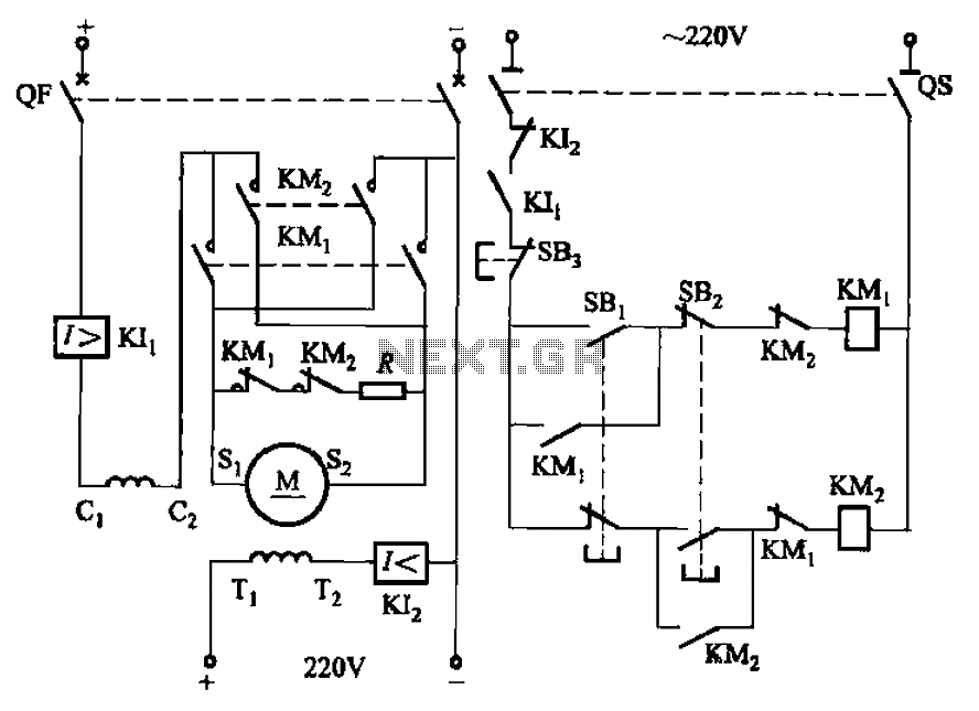
The circuit depicted in Figure 3-194 features a re-excitation type DC motor with six terminals: S1 and S2 for the armature windings; C1 and C2 for the series excitation (field) windings; and T1 and T2 for the shunt (field)...