
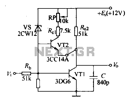
50Mhz Rf Bridge Circuit

The described bridge circuit is designed specifically for measuring the impedance of 50-MHz amateur radio antennas, which is crucial for ensuring optimal performance and matching in radio frequency (RF) applications. The circuit employs a potentiometer, Rl, with a resistance of 500 ohms, allowing for fine adjustments in the measurement process. This miniature potentiometer facilitates the balancing of the bridge, enabling accurate readings of the unknown impedance.
In the configuration, the unknown impedance is compared against a known resistor, R2, which has a value of 51 ohms. This comparison is essential for determining the characteristics of the antenna under test. The use of a known resistor provides a reference point, allowing the user to calculate the unknown impedance based on the bridge's balance condition.
An external signal source is necessary to provide the excitation signal for the bridge circuit. This signal source generates a test frequency of 50 MHz, which is the operational frequency of the amateur radio antennas being measured. The signal is applied across the bridge, and the resulting voltage readings are analyzed to determine the impedance characteristics.
The overall design of the bridge circuit must ensure minimal signal loss and distortion at the operating frequency. Proper layout and component selection are critical to maintaining the integrity of the measurements. Additionally, care should be taken to minimize parasitic capacitances and inductances, which can adversely affect the accuracy of the readings.
In summary, this bridge circuit serves as a vital tool in the characterization of 50-MHz amateur radio antennas, leveraging a combination of a linear potentiometer and a known resistor to facilitate precise impedance measurements, supported by an external signal source for effective operation. The bridge shown was used for measurements on 50-MHz amateur radio antennas. Rl is a miniature 500 linear potentiometer. The unknown impedance is compared to R2, a 51- resistor. An external signal source is required.
Related Circuits
Various sawtooth voltage generators utilize the principle of capacitor charging and discharging to produce sawtooth waveforms in both forward and reverse directions. A simple sawtooth voltage generator circuit is straightforward in design; however, it suffers from poor linearity in...
A field effect transistor (FET), designated as Q1, functions within the linear resistive region to facilitate automatic gain control. The attenuation of the RC network is one-third at the oscillation frequency with zero phase shift, necessitating that the amplifier...
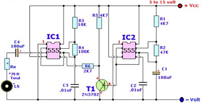
Browse home alarm circuit explanation latest schematic siren wailing with latest Wailing Alarm Siren circuit schematic with explanation. The loudspeaker LS and the resistor marked Rx should be together 75 ohms. If a standard 8-ohm speaker is used, then...

This is a simple hobby circuit for a remote-controlled toy car. The primary component utilized is the IR sensor circuit, which includes a TSOP IR receiver. This receiver allows the user to start and stop the DC motor of...

This article discusses a simple 5-channel radio remote control circuit utilizing the TX-2B and RX-2B integrated circuits from Silan Semiconductors. The TX-2B/RX-2B is a remote encoder-decoder pair suitable for remote control applications. It features five channels, a wide operating...
The objective is to enhance information transmission through the distribution of articles. Please contact us via email at [email protected] within 15 days if there are any issues related to article content, copyright, or other concerns. Prompt deletion will occur...