
50w audio amplifier using ic tda1562

The integrated output amplifier is designed to operate efficiently within the constraints of automotive and battery-powered environments. The simplicity of the circuit is a significant advantage, reducing the complexity and potential points of failure often associated with audio amplification systems. The use of only one integrated circuit minimizes the physical footprint of the amplifier, making it suitable for compact installations within vehicles or portable devices.
The Class-H operation of the amplifier is particularly noteworthy, as it allows for improved efficiency by modulating the supply voltage according to the output signal requirements. This operation mode can enhance audio fidelity while reducing power consumption, a critical consideration in battery-operated applications. The inclusion of decoupling capacitors (C5 and C6) is essential for maintaining stability and performance, filtering out voltage spikes and noise that could otherwise affect the audio output.
The mute and standby functionalities provide flexibility in usage, allowing the amplifier to conserve power when not actively amplifying audio signals. The design ensures that the transition from mute to operational mode is smooth and free of audible artifacts, enhancing the user experience. The low standby current of 200 µA is particularly advantageous, as it extends the battery life of the devices in which the amplifier is employed.
The switched RC network (R4-C4) not only facilitates the mute and standby functions but also serves as a safeguard against audible clicks or pops that can occur during power-up. This careful consideration in design reflects a commitment to audio quality and user comfort.
Overall, this integrated output amplifier represents an efficient and effective solution for audio amplification in constrained environments, combining simplicity, reliability, and advanced features to meet the demands of modern electronic applications.The integrated output amplifier described in this article consists of little more than one integrated circuit. It is intended especially for use in motor vehicles and other battery-operated applications. Although it appears simple and hardly worth looking at, the amplifier can produce an appreciable audio power output.
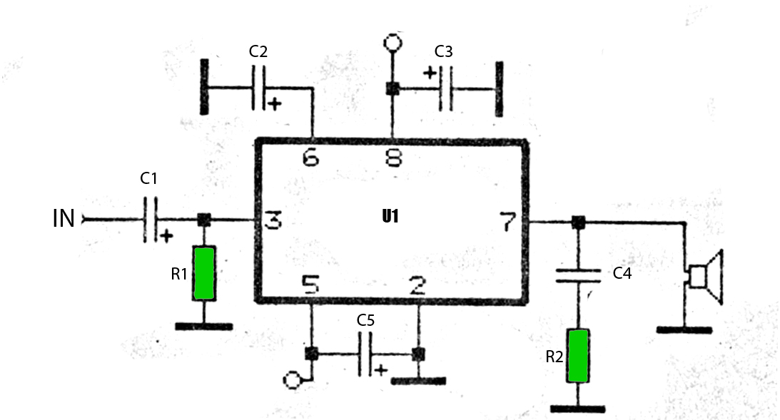
The circuit diagram in Figur e 2 emphasizes how few external components are needed to construct a complete output amplifier. For instance, the new device does not need compensation networks to enhance the stability. Also, because of the absence of switch-on phenomena, there is no need for a switch-on delay network. There is, of course, still a need for supply line decoupling capacitors. Capacitors C5 and C6 are required for Class-H operation, about which more in the box. The value of input capacitors C1 and C2 is relatively low, thanks to the high input impedance of the IC. Switched RC network R4-C4 at the mode select` input (pin 4) serves to switch the IC to mute` or standby`.
When the supply voltage is switched on, the IC is first switched automatically to the mute` mode and to on` only after a short delay. The time constant R4-C4 is a few tenths of a second and this delay between the two states is sufficient to obviate disturbing (and annoying) switch-on phenomena.
Switch S1 enables the amplifier to be switched to standby` when the use of the amplifier is not needed for a period of time. When that time has elapsed, the amplifier is quickly reverted to normal operation. The current drain in the standby mode is virtually negligible at only 200 µA. Resistor R3 prevents a short-circuit current ensuing when S1 is being closed at the instant C4 is being discharged.
🔗 External reference
Related Circuits
This circuit is a 20W Audio Amplifier kit, based on the TDA2005 IC, a class B dual audio amplifier, specifically designed for car radio applications etc. Power supply - 18 VDC. Output power - 20 W, 4 ?. IC...
The car power amplifier utilizes the SI1050GL integrated circuit (IC) as the primary amplification component. It delivers an output power of 50 Watts at an 8-ohm mono impedance. The amplifier operates with a DC voltage of up to 25...
This mini audio amplifier will test the audio stages in amplifiers such as the front end of FM bugs. You can also use it on lots of our other projects as well as the output stages of radios. It...
The following segment provides the enhanced Motorola schematic for a typical application of the MRF141G, which includes parasitic stabilization features. The MRF141G is a broadband power RF MOSFET capable of delivering a conservatively rated 300 watts across the FM...
The standard Class AB audio power amplifier allows for direct coupling of the amplifier's output to speakers. This is beneficial as it eliminates capacitors or transformers that could compromise sound quality. The speakers are connected directly to the amplifying...

A very simple LED torch can be designed using the NSI45090JDT4G adjustable constant current regulator (CCR) from ON Semiconductor, utilizing very few external components. The NSI45090JDT4G device provides a cost-effective solution for regulating current in LEDs. This constant current...