
300 Watt MOSFET Broadband Amplifier Using MRF141G

The MRF141G RF MOSFET operates within the FM broadcast band and requires careful thermal management due to its high power output capabilities. The specified heat spreader, made from a 5/16" thick copper plate measuring 6" x 8", is essential for dissipating heat generated during operation. Proper mounting to the heatsink with 6-32 machine screws ensures stable thermal performance.
The variable gain control via a bias adjustment trim pot allows for fine-tuning of the amplifier's output, which is critical for optimizing performance based on specific application needs. The integration of an SWR bridge circuit is a prudent design choice, as it provides real-time monitoring of the standing wave ratio, allowing for proactive management of the amplifier's output power. This feature is particularly important in scenarios where the antenna may be compromised, preventing potential damage to the amplifier and associated components.
For added safety, the implementation of a power supply cutoff relay is recommended, particularly in systems where a loss of PLL lock could lead to uncontrolled output. This relay acts as a failsafe, ensuring that the amplifier is powered down in critical situations, thereby protecting both the equipment and the operator.
The operational safety warnings highlight the importance of handling high-power RF equipment with care. The risk of RF burns from exposed coaxial connections necessitates protective measures, such as insulated tools and proper safety gear during installation and maintenance. Furthermore, the potential fire hazard from a roof-mounted antenna during adverse weather conditions underscores the need for robust installation practices and regular inspections to mitigate risks associated with environmental factors.
Overall, the MRF141G amplifier requires meticulous attention to detail in its design, installation, and operation to ensure optimal performance and safety.The following segment will provide the enhanced Motorola schematic for any typical application for the MRF141G (which includes parasitic stabilization features), a broadband power RF MOSFET which will place out a conservatively-rated 300 watts across the FM broadcast band. The flange about the MRF141G ought to be mounted to a heat spreader, a copp er plate 5/16" thick and 6" x 8", which is then mounted to the heatsink with 6-32 machine screws, if your heatsink is drilled and tapped. I recommend getting the two transformer assemblies, instead of trying to create them, due to the fact 15-ohm hardline is not straightforward to come across.
I`ve had great results ordering them from: This amplifier has the notable attribute of variable acquire manage via the bias adjustment trim pot. It may possibly be used in conjunction with an SWR bridge circuit to limit energy output inside the event of large SWR triggered by harm towards the antenna in the course of a storm, or a person inadvertently disconnecting the coax transmission line.
For those who wish to apply a failsafe shutdown system that is triggered by reduction of PLL lock, I nevertheless suggest a power provide cutoff relay for total basic safety having said that. CAUTION: This amplifier operates at very high power ranges. You are able to obtain severe RF uses up if coming in contact with open coax feeder from this amp. Moreover, if your broadcast antenna is roof-mounted, and it need to blow down inside a windstorm although fed at full power from this amp, it may possibly commence a fire in certain sorts of roofing insulation!
Be extremely cautious with all the utilization, set up and operation in the unit. 🔗 External reference
Related Circuits
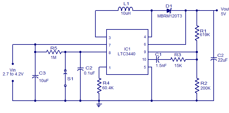
A simple 5V boost converter utilizing the LTC3440 is presented. The LTC3440 is a high-efficiency DC to DC converter capable of operating with input voltages that are below, above, or equal to the output voltage. With synchronous rectification, the...
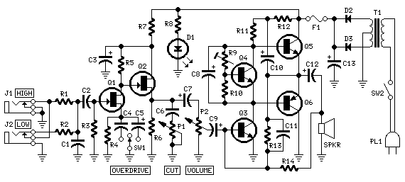
The objective of this design is to create a Combo amplifier that was popular during the 1960s and 1970s. It is particularly effective as a guitar amplifier but can also perform well with various electronic musical instruments or microphones....
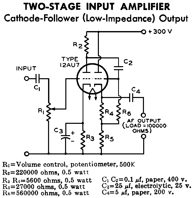
12AU7 (ECC82) Cathode Follower Tube Preamplifier Schematic. This is a two-stage 12AU7 preamplifier featuring a low impedance output stage. The overall gain is approximately 8 times. The 12AU7 (ECC82) tube is a dual triode commonly used in audio applications due...
To configure the amplifier, set resistor R1 to its maximum value and resistor R12 to zero. After this adjustment, power on the amplifier. Adjust R1 until the measured output offset is between 30 mV and 100 mV. Once this...
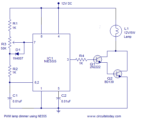
A simple PWM lamp dimmer using the NE555 timer IC. The 555 timer IC is configured as a variable duty cycle astable multivibrator to control the brightness of the lamp. The described circuit utilizes the NE555 timer IC, a versatile...
The following circuit illustrates a power supply for an amplifier circuit diagram. Features include ease of construction and adequate electrical response. The power supply circuit for an amplifier is a crucial component that ensures the amplifier operates effectively. It typically...