
5474 tips

The Aristo ART-5474 Accessory Panel serves as an essential component in model train control systems, allowing for versatile accessory management. Its design caters to the needs of hobbyists who require precise control over multiple devices. The ability to manage two turnouts and additional functions such as lighting and sound effects enhances the operational experience of model railroads.
The layout and arrangement of the components within the ART-5474 are optimized for ease of use. The clearly marked terminals facilitate straightforward connections, while the LED indicators provide immediate feedback on the operational status of the unit. This design consideration helps users diagnose issues quickly during setup or operation.
The limitations associated with the ART-5474, particularly regarding the non-isolation of certain outputs, highlight the importance of adhering to specified wiring practices. Users must ensure that the loads connected to outputs A, B, and C do not interfere with each other to prevent potential damage to the unit. The isolation of outputs D and E through optical isolators provides a useful feature for more complex wiring configurations, allowing for increased flexibility in system design.
For optimal performance, users may consider experimenting with the antenna configuration, particularly in environments where signal reliability is critical. While the internal antenna is effective, extending the antenna externally may yield better results in specific scenarios. Care should be taken when modifying the unit, as improper adjustments could lead to malfunctions.
Overall, the ART-5474 offers a robust solution for controlling model train accessories, combining functionality with user-friendly features. Its specifications and operational guidelines provide a solid foundation for effective integration into model railroading systems.The Aristo ART-5474 Accessory Panel is a complete receiver intended to control accessories through the use of the A through E buttons on the Train Engineer transmitter. As the 5474 comes, it will control two turnouts, one constant load such as lights, and trigger two low current devices as the bell and whistle of many sound systems.
Sometime in the future, there is also an ART-5475 receiver that is essentially identical, except that it is wired to control turnouts on all five outputs. Note that the current (through 1999) version of the ART-5474 DOES NOT have a scanning receiver so that it will work with the 10 channel Train Engineer ONLY on frequency #1.
The unit is 4-1/4"" long by 2" wide by 7/8" high. The power connector extends from one end and needs an additional 1-3/4" of clearance to allow the connector to be removed. The screw type output terminals accept stripped wires and are arranged on the other end of the unit. A red LED on the top of the unit indicates power. A green LED indicates that the receiver is receiving a command. A push button allows the address code to be set. The unit does have some operational and usage limitations which are not revealed in the instruction sheet that comes with the unit.
The main one is that the power input and the A, B and C outputs are NOT ISOLATED from each other. This means that you CANNOT cross connect wires between these terminals on any individual 5474 or between 5474`s. The D and E outputs are isolated with optical isolators and can be cross connected. The output current capability of all of the outputs is limited. The turnout control outputs ("A" and "B") source a pulse of power but will only drive one turnout motor reliably.
Some people have driven two, but then others have had their 5474`s fail under these conditions. The "C" output provides switched DC power and is rated at 200 mA, however my analysis shows that it is good for only 100 mA before the internal 10 ohm current limiting resistors will overheat. Also, neither output terminal is common to any other lead so that your load MUST float with respect to all other leads except the "D" and "E" outputs.
Outputs "D" and "E" are optically isolated bipolar transistors that will sink only about 10 mA. These outputs are polarity sensitive so that if they don`t trigger your sound system, try reversing the leads. The antenna for the 5474 is internally connected to one of the power leads. If you want to convert the 5474 to an external antenna then you need to cut a trace on the printed wiring board and install a 3` or so piece of wire to the hole marked "ANT.
" This hole is right next to the power connector. Cut the trace leading from that hole to the input inductor to isolate the antenna terminal from the DC power wires. I use five ART-5474`s in my control panel for the GIRR and these provide adequate range and sensitivity.
However, the one that I have moved between my Atlantic and RS-3 has provided inadequate range. I use it to control the bell and whistle, but at more about 10`, control gets flaky. The one that I installed in my Pacific often didn`t work at 1` range. The units on the control panel use their power leads for their antennas. All five units are wired from a 12 volt DC power supply and there is about 10` of wire between the 5474`s and the power supply. This wire acts as an antenna and I get reliable control anywhere on my layout, even in the garage on the other side of the house.
By experiment with the unit in the RS-3, I found that if I disconnected the antenna lead from the power lead and extended the antenna to 10`, it worked pretty well. However dragging a 10` wire behind the engine isn`t entirely practical. I did find that on my particular unit, I could improve the sensitivity by tweaking on the RF transformer, T2, at the input to the unit.
I DO NOT recommend that you try this unless you know what you are doing, because you could "tweak" the unit i 🔗 External reference
Related Circuits
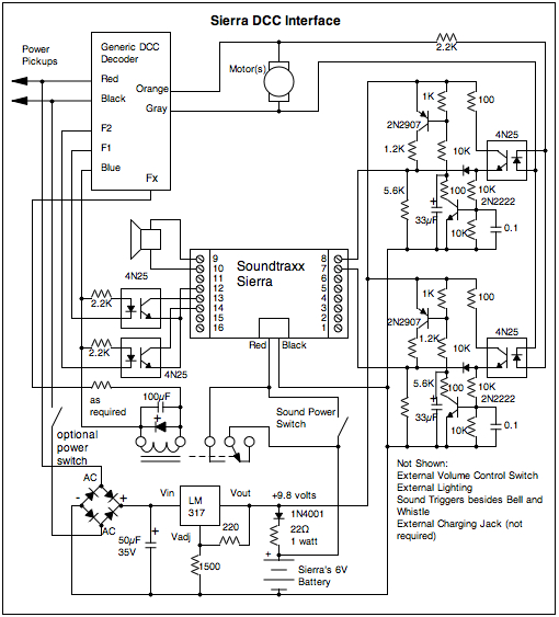
This document outlines the installation and operation of a Soundtraxx Sierra sound system. The Sierra performed adequately and was reasonably priced; however, it was discontinued in September 2008 without a direct replacement. A Soundtraxx Sierra sound system was purchased...
After extensive reading and discussion, plans have been finalized for the construction of a single-ended 300B integrated amplifier. The circuit... The single-ended 300B integrated amplifier is a popular choice among audiophiles due to its warm sound and high fidelity. The...
The Bachmann Big Hauler locomotive has significantly improved in appearance, reliability, and noise level over the past few years. However, the sound system remains basic, providing a poor imitation of exhaust sounds in the form of a chuff synchronized...
This article demonstrates how to create a simple yet effective static electricity generator. This device enables the user to carry a constant static charge on their body and discharge it onto anything grounded or of opposite polarity. The generated...
The streamliner passenger car was introduced just before World War II as part of dedicated passenger car and locomotive sets. These cars were designed to be lightweight, enabling high speeds with a relatively small diesel engine. Over time, railroads...
A used USAT F3A has come into possession. This was unexpected, but it adds another locomotive to the GIRR collection. The model is designated with the road number 26C. According to the ATSF numbering scheme from that period, this...