
555 audio oscillator Analog Integrated Circuits

The 555 timer IC is widely recognized for its reliability and ease of use in generating timing and oscillation functions in electronic circuits. In the astable multivibrator configuration, the circuit continuously switches between two states, making it ideal for applications like flashing LEDs, tone generation, and pulse-width modulation.
The circuit consists of three main components: the 555 timer IC, a capacitor (C), and two resistors (R1 and R2). The values of these resistors and the capacitor determine the frequency of oscillation and the duty cycle of the output signal. The charging and discharging paths through the resistors create a time delay that results in the LED blinking at a specific rate.
The capacitor charges through both resistors R1 and R2 when the output is high and discharges only through R2 when the output is low. This asymmetrical charging and discharging lead to a duty cycle that can be adjusted by varying the resistor values. The output frequency can be calculated using the formula:
\[ f = \frac{1.44}{(R1 + 2R2)C} \]
Where:
- \( f \) is the frequency of oscillation,
- \( R1 \) is the resistance in series with the capacitor,
- \( R2 \) is the resistance through which the capacitor discharges,
- \( C \) is the capacitance.
By selecting appropriate values for R1, R2, and C, one can tailor the frequency and duty cycle to suit specific applications. The duty cycle can be calculated as:
\[ Duty\ Cycle = \frac{R2}{R1 + 2R2} \times 100\% \]
This relationship allows for fine-tuning of the circuit for various applications, such as creating different flashing patterns for LEDs or generating specific audio tones. The 555 timer's versatility makes it a fundamental component in many electronic projects, providing a simple and effective solution for timing and oscillation needs.The 555 integrated circuit is a general-purpose timer useful for a variety of functions. In this experiment, we explore its use as an astable multivibrator, or oscillator. Connected to a capacitor and two resistors as shown, it will oscillate freely, driving the LEDs on and off with a square-wave output voltage. This circuit works on the princip le of alternately charging and discharging a capacitor. The 555 begins to discharge the capacitor by grounding the Disch terminal when the voltage detected by the Thresh terminal exceeds 2/3 the power supply voltage (Vcc). It stops discharging the capacitor when the voltage detected by the Trig terminal falls below 1/3 the power supply voltage.
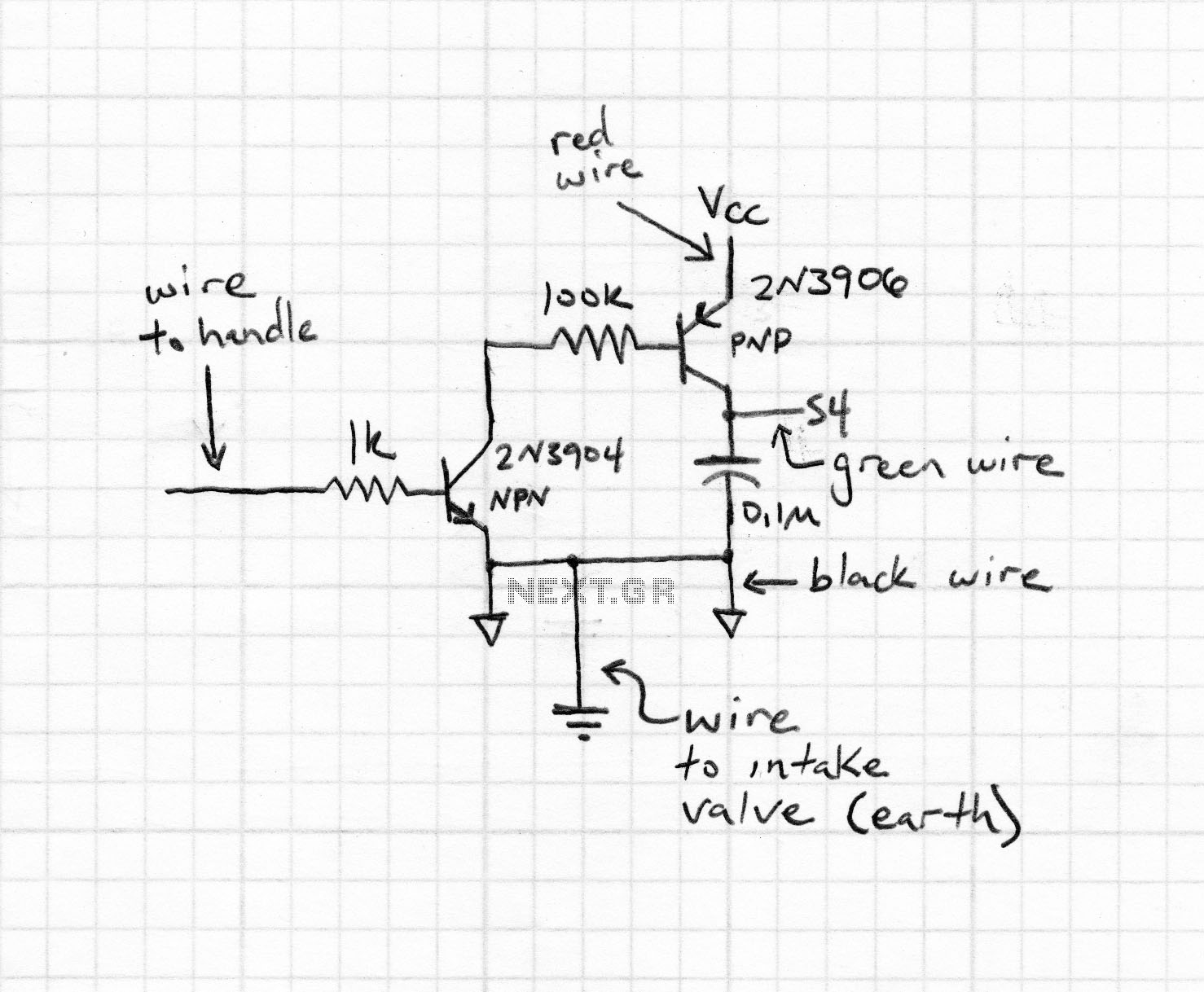
Thus, when both Thresh and Trig terminals are connected to the capacitor`s positive terminal, the capacitor voltage will cycle between 1/3 and 2/3 power supply voltage in a "sawtooth" pattern. During the charging cycle, the capacitor receives charging current through the series combination of the 1 M © and 100 k © resistors.
As soon as the Disch terminal on the 555 timer goes to ground potential (a transistor inside the 555 connected between that terminal and ground turns on), the capacitor`s discharging current only has to go through the 100 k © resistor. The result is an RC time constant that is much longer for charging than for discharging, resulting in a charging time greatly exceeding the discharging time.
The 555`s Out terminal produces a square-wave voltage signal that is "high" (nearly Vcc) when the capacitor is charging, and "low" (nearly 0 volts) when the capacitor is discharging. This alternating high/low voltage signal drives the two LEDs in opposite modes: when one is on, the other will be off.
Because the capacitor`s charging and discharging times are unequal, the "high" and "low" times of the output`s square-wave waveform will be unequal as well. This can be seen in the relative brightness of the two LEDs: one will be much brighter than the other, because it is on for a longer period of time during each cycle.
The equality or inequality between "high" and "low" times of a square wave is expressed as that wave`s duty cycle. A square wave with a 50% duty cycle is perfectly symmetrical: its "high" time is precisely equal to its "low" time.
A square wave that is "high" 10% of the time and "low" 90% of the time is said to have a 10% duty cycle. In this circuit, the output waveform has a "high" time exceeding the "low" time, resulting in a duty cycle greater than 50%.
Use the audio detector (or an oscilloscope) to investigate the different voltage waveforms produced by this circuit. Try different resistor values and/or capacitor values to see what effects they have on output frequency or charge/discharge times.
🔗 External reference
Related Circuits
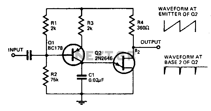
With the component values shown, the oscillator has a frequency of 8 kHz. When an input signal is applied to the base of Q1, the current flowing through Q1 is varied, thus affecting the time required to charge C1....
The audio ground is completely isolated from the digital ground. The top copper layer is utilized as a shield for both the audio and digital ground, which aids in preventing the audio section from picking up noise from the...

There have described the involvement benefited LM3909 circuit, which is quite expensive. That's why I prefer to use a much cheaper known timer 555th. Involvement of the tree is a very simple scheme is to figure 2. It is...
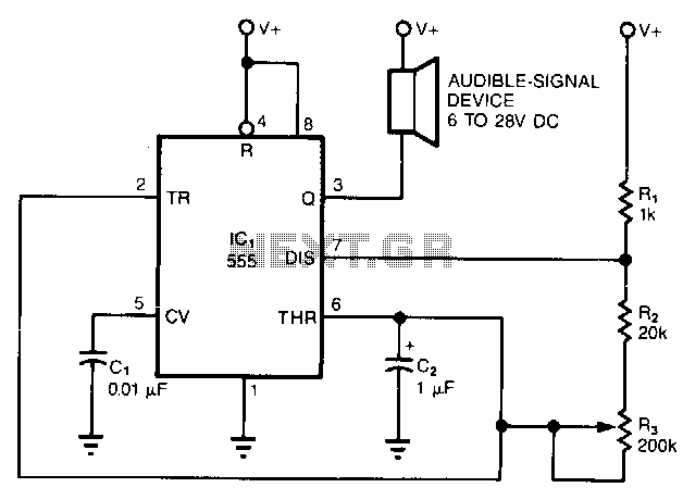
The simple circuit converts the continuous beep of an audible-signal device, such as a Mallory sonalert, into a unique warble or chirp. The values of resistor R and capacitor C2 determine the specific tone quality produced. With a 1kΩ...
Graphic equalizers consist of 15 or 30 band-pass filters, each corresponding to a 1/3 octave frequency. Traditional equalizer designs utilize standard discrete components to implement these band-pass filters. The Apex GX and PE series have demonstrated superior performance by...
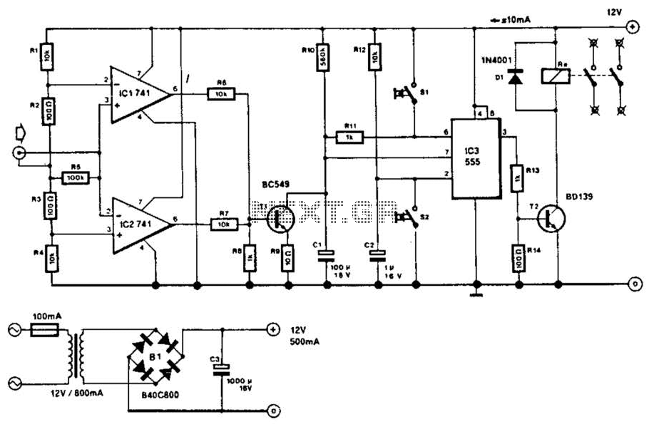
This circuit will disconnect the line supply to audio or video equipment if there has been no input signal for approximately 2 seconds. Switch SI provides manual operation, while switch S2 functions as a reset mechanism. This circuit allows...