
Simple voltage controlled oscillator

The described oscillator circuit operates at a frequency of 8 kHz, determined by the selected component values. The key component, Q1, functions as a transistor that modulates the current flowing through it in response to an input signal applied to its base. This modulation directly influences the charging time of capacitor C1, which is critical for establishing the oscillation frequency.
The phase inversion characteristic of transistor Q1 is significant; it introduces a 180-degree phase shift between the input signal and the output signal. This means that when the input signal reaches its peak, the output signal is at its trough, effectively inverting the waveform. This behavior is essential in various applications, particularly in timing circuits and waveform generation.
Furthermore, the output from this oscillator can be utilized to trigger a bistable flip-flop. A bistable flip-flop is a type of digital memory circuit that has two stable states and can be used to store binary information. The oscillator's output provides a clock signal that can toggle the state of the flip-flop, allowing for precise control in digital applications, such as counters, registers, or state machines.
In summary, this oscillator circuit not only generates an 8 kHz signal but also offers versatility in digital logic applications by providing a phase-inverted output that can effectively trigger bistable flip-flops. The design's simplicity and effectiveness make it a valuable component in various electronic systems.With the component values shown, the oscillator has a frequency of 8 kHz. When an input signal is applied to the base of Ql the current flowing through Ql is varied, thus varying the time required to charge Cl. Due to the phase inversion in Ql the direction of output frequency change is 180 degrees out of phase with the input signal
The output may be used to trigger a bistable flip-flop.
Related Circuits
If you have ever wanted a high-voltage generator to create impressive lightning effects, conduct Kirlian photography experiments, or experiment with neon lights, this project is ideal. It describes a laboratory pulse generator utilizing an auto-ignition coil, capable of delivering...
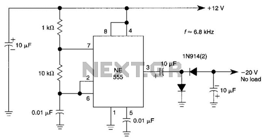
This DC negative-voltage generator based on the 555 produces a negative output voltage equal to approximately 2 times the DC supply voltage. The described circuit utilizes the popular 555 timer IC configured in an astable or monostable mode to generate...
A typical Colpitts oscillator design. This circuit operates similarly to the Hartley oscillator, but the Colpitts LC tank circuit consists of a single inductor and two capacitors. The capacitors effectively form a single tapped capacitor instead of the tapped...
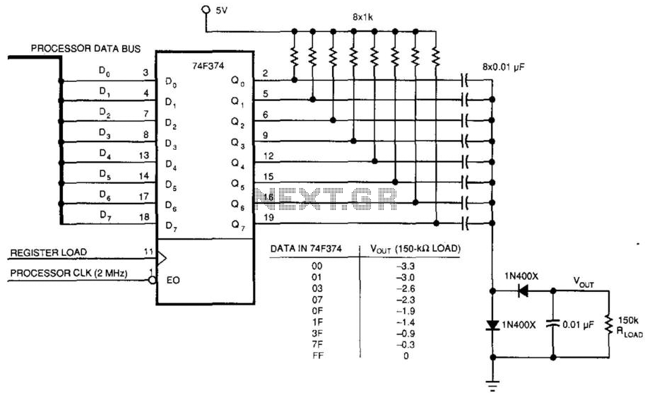
This circuit was used to produce a variable negative voltage for contrast control of an LCD display. A 74F374 generates a square wave that is AC coupled to a rectifier and load. By using the microprocessor clock and data...
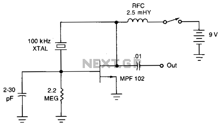
The JFET Pierce oscillator is stable and straightforward. It can serve as the clock for a microprocessor, a digital timepiece, or a calculator. With a probe connected to the output, it can function as a precise injection oscillator for...
When the push button is pressed, a clock pulse appears on the CLK input of flip-flop IC1b. The output then toggles, causing the LEDs to turn off. Simultaneously, IC1a is reset, silencing the buzzer. Pressing the button again will...