
555-based solar engine

The circuit described is a phototropic device known as a photopopper, which is designed to respond to light in a specific manner. The simplification of the original circuit implies that unnecessary components were removed or optimized to enhance functionality while reducing complexity. A phototropic circuit typically utilizes light-dependent resistors (LDRs) or phototransistors to sense ambient light levels.
In the configuration of the photopopper, it is likely that two or more phototropic sensors are employed to detect light intensity from different angles or sources. This dual approach allows the circuit to react to light changes more effectively, enabling it to perform actions such as activating an output device, which could be a motor or LED, in response to light exposure.
The doubling of the circuit may involve mirroring the original design to create a balanced response to light stimuli, allowing for enhanced sensitivity and faster activation times. The output stage of the circuit might include a transistor or a relay to control a higher power load, ensuring that the photopopper can drive substantial devices while remaining controlled by the low-power phototropic sensors.
Overall, the photopopper design is an innovative approach to creating a responsive electronic system that can react to environmental light changes, with applications ranging from simple educational projects to more complex automated systems in robotics or lighting control.Wilf Rigter simplified this circuit a bit, made it phototropic, and doubled it up to yield a photopopper design in a post later the same day. I`ve got this design written up elsewhere in the library. 🔗 External reference
Related Circuits
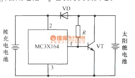
This is a solar charger circuit designed to charge Lead Acid or Ni-Cd batteries using solar energy. The circuit captures solar energy to charge the batteries. The solar charger circuit typically consists of several key components, including a solar panel,...
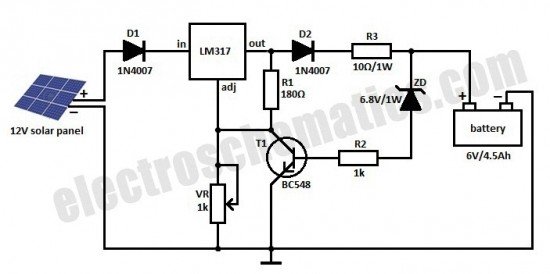
The following circuit illustrates a current-limited solar battery charger circuit diagram. This lead-acid or Ni-Cd battery charger circuit diagram utilizes solar energy to charge a 6-volt, 4.5 Ah rechargeable battery for various applications. It represents a straightforward solar battery...
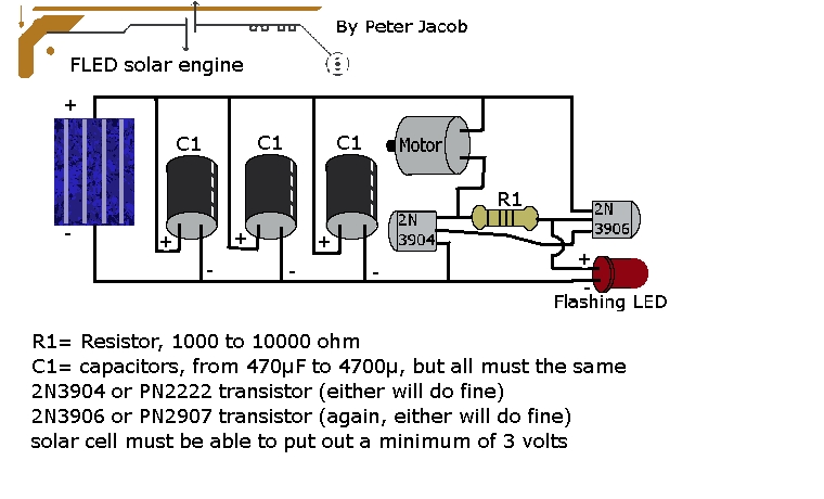
This document outlines the construction of a trimet. The required components include three capacitors, a 2N3904 transistor, a 2N3906 transistor, a resistor with a value between 1k to 10k ohms, and a solar cell with a minimum voltage of...
It is possible to reduce electricity bills by utilizing alternative power sources. The photovoltaic module, or solar panel, described here, can produce a power output of 5 watts. Under full sunlight conditions, the solar panel generates 16.5V and can...

This is a power generating method from sunlight. This method of power generation is simple and is taken from natural resource. This need only maximum sunlight to generate power. This project helps for power generation by setting the equipment...
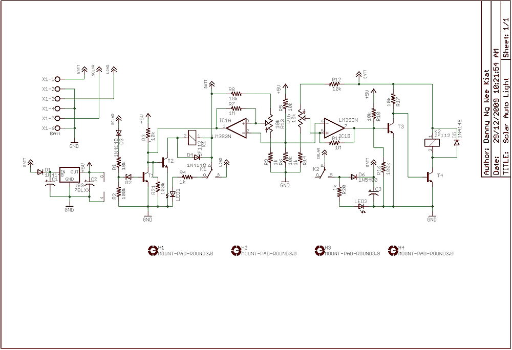
Few years back, I had been working on a project for solar auto lighting. The light will turn on when the solar panel voltage drop below a set point indicating that it is dark. The detection is done by...