
Solar Charger circuit

The solar auto lighting project employs a solar panel as the primary energy source, which charges a battery that powers the lighting system. The operation of the circuit hinges on the voltage levels produced by the solar panel, which are monitored to determine the ambient light conditions. A zener diode (D2) is incorporated into the circuit to establish a reference voltage for the light detection mechanism. The zener diode's breakdown voltage is selected to facilitate the transition of the circuit state when the solar panel voltage drops below a predetermined threshold, indicating that it is dark.
Relay K1 plays a crucial role in controlling the load and the battery connection. It is designed to disconnect the load if the battery voltage falls below a specified threshold, preventing over-discharge of the battery and ensuring its longevity. This relay is actuated by a comparator that continuously monitors the battery voltage, enabling automatic disconnection when necessary.
Relay K2 is utilized to manage the charging process of the battery. It operates in conjunction with the comparator, which assesses the battery voltage and determines when it is appropriate to halt the charging. This relay ensures that the battery is not overcharged, thus maintaining optimal battery health and performance.
The comparator circuit is central to the functionality of the entire system, as it performs real-time voltage comparisons to trigger the relays based on the set thresholds for both light detection and battery management. The design of this circuit allows for efficient solar energy utilization while providing a reliable automatic lighting solution that responds dynamically to environmental conditions.Few years back, I had been working on a project for solar auto lighting. The light will turn on when the the solar panel voltage drop below a set point indicating that it is dark. The detection is done by using D2 in the schematic. The zener diode value will be adjusted so that the transition between the switch depends on the amount of light the panel receive.
Relay K1 is used to switch the load and the battery. If the battery power fall below a set threshold, the relay will cut the supply to the load. Relay K2 is used to control the charging of the circuit. When a Set point is reach the charging will be cut off. A Comparator is used for the voltage comparison. 🔗 External reference
Related Circuits
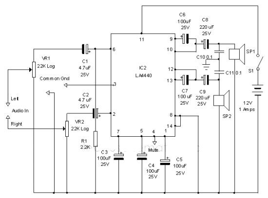
The LA4440 audio amplifier IC can be utilized to design a straightforward stereo power audio amplifier project, capable of delivering 6 watts of output power into an 8-ohm load. This audio amplifier IC features a minimal number of external...
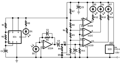
All distances mentioned can vary depending on the infrared transmitting and receiving LEDs used and are significantly affected by the color of the reflecting surface. Black surfaces greatly reduce the device's sensitivity. This circuit can also be applied in...
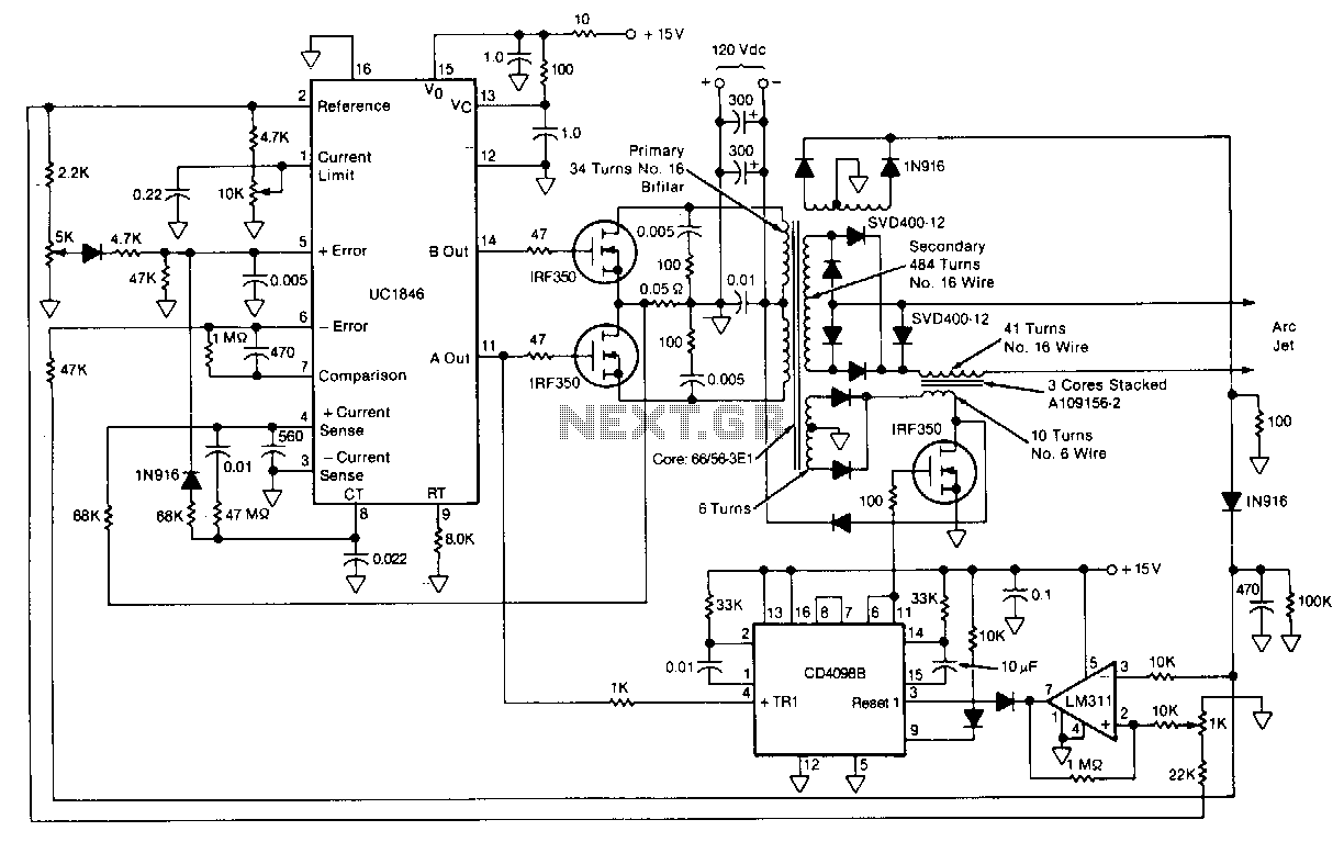
This circuit for starting arc jets and controlling them in steady operation is capable of high power efficiency and can be constructed in a lightweight form. The design comprises a pulse-width-modulated power converter, which is configured in a closed...
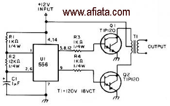
The first section of the 555 timer is configured as an astable oscillator, with R2 and C1 determining the frequency. The output is accessible at pin 5. The second section functions as a phase inverter, with its output available...
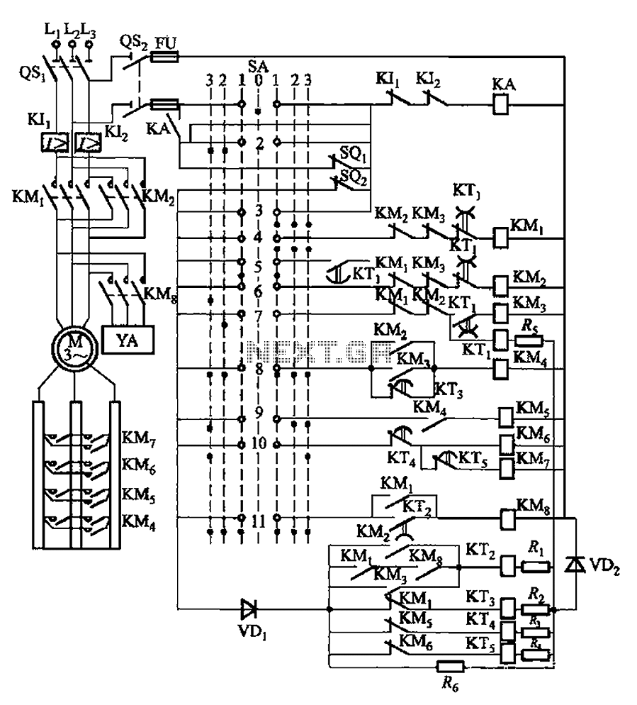
The system involves a master controller and a PQS1 Series Magnetic control panel, which includes a control circuit designed to manage the bridge crane hoist lifting mechanism. The master controller handle SA features seven positions: alongside the zero position,...
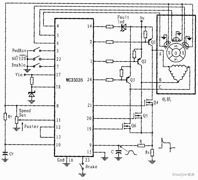
The presented three-phase application circuit features a motor controller circuit connection diagram that operates using a full-wave six-step method. The power switch is a Darlington PNP type, while the lower power switch is an N-channel power MOSFET. Each device...