
555 capacitor filter circuit diagrams

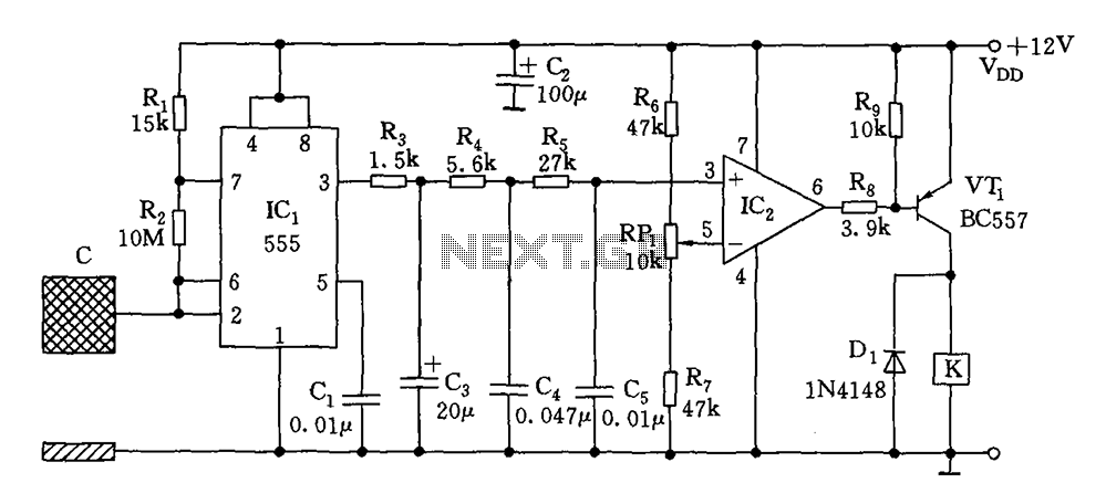
The described circuit utilizes an astable multivibrator configuration to generate a square wave that serves as a timing reference for the subsequent monostable circuits. The astable multivibrator, composed of IC1, R1, and C2, continuously oscillates, resulting in a periodic output that is essential for triggering the monostable circuits (IC2, IC3, IC4). These monostable circuits respond to the square wave output by generating a single output pulse whose width is contingent upon the charging and discharging characteristics of their respective capacitors.
The measured capacitance (Cx) is compared against predefined limits (Cm and Cn). The circuit effectively determines if the measured capacitance falls within acceptable bounds. If Cx exceeds Cm, LED1 activates, signaling that the capacitance is above the minimum threshold. Conversely, if Cx is lower than Cn, LED2 activates, indicating that the capacitance exceeds the maximum threshold. The NAND gates serve as a logical check to ensure that the output conditions are met before allowing the 555 timer to set, thus controlling the overall operation and indicating the status of the capacitor being tested.
In conclusion, this circuit provides a robust solution for capacitance measurement and qualification, utilizing standard IC components to achieve the desired functionality. The use of visual indicators (LEDs) enables easy interpretation of the test results, while the design ensures reliability and precision in capacitance evaluation. Capacitor filter works by the capacitance being measured is proportional to the pulse width and pulse width qualifying nominal capacitance comparing screening to detect. Circui t shown in Figure, IC1 and R1, C2 composition astable multivibrator, a period of about 1.4 seconds to produce a square wave pulse. In IC2, IC3, IC4 as the core component monostable trigger circuit, the timing of the trigger pulse width depending on their charge and discharge time constants.
Cx is measured capacitance, Cm, Cn is qualified capacitor capacitance of the upper and lower limit. That Cm Cx Cn. IC2, IC3, IC4 by IC1 output with square wave trigger, resulting in their different width, comparing the door circuit. Then trigger IC5, IC6 monostable circuit, the NAND gate 6,7 if not negative output pulses, 555 will not be set, 3 feet was low, VT1, VT2 off, LED1, LED2 are not light indicating that the capacitor under test qualified.
If LED1 luminous flash indicating Cx is greater than Cm; if LED2 luminous flash indicating that less than Cx Cn, capacity overrun. IC5, IC6 one-shot pulse generating about 0.8 seconds.
Related Circuits
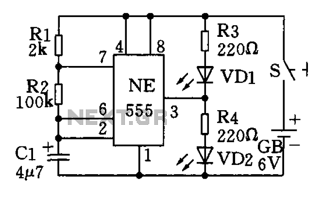
The circuit utilizes a 555 timer as the central component of a flashing light circuit. In normal operation, the light-emitting diodes (LEDs) VD1 and VD2 alternate flashing. The circuit comprises the NE555 timer, resistors R1 and R2, and capacitor...
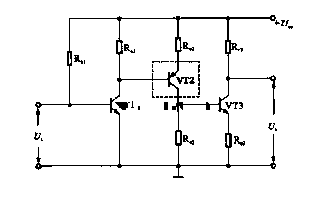
A multi-stage DC-coupled amplifier circuit utilizes NPN type transistors. Each stage is designed to achieve an appropriate operating point at the base, resulting in a stepwise increase in collector potential, which subsequently reduces the final output voltage range. To...

Connect the components, ensuring to pay attention to the connections for the transistor. The 22-ohm load resistor and thermistor should be connected in a manner that allows for good thermal contact. Note: If using the Light Application Adapter, REFIN-...
The switch circuit consists of a capacitive oscillator, an integration network, and a comparator circuit that controls a relay. When a body comes close to the induction plate, the inductive capacitance to ground increases, causing the 555 astable multivibrator...
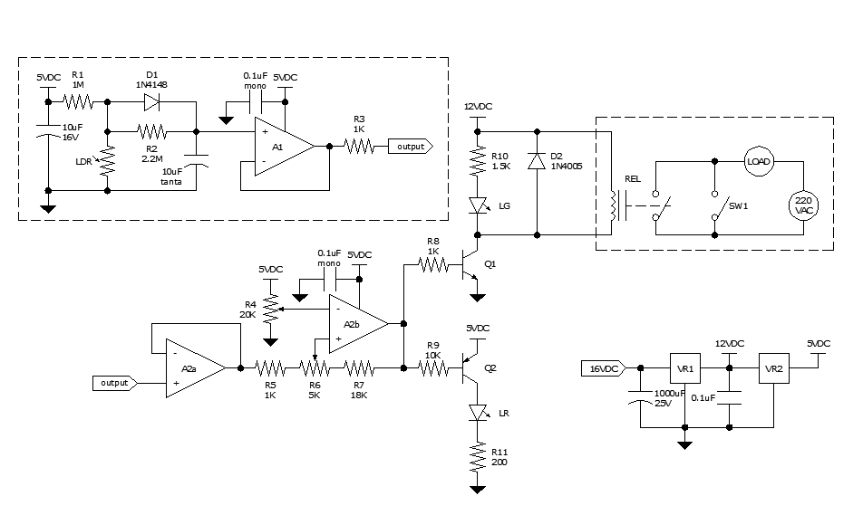
Approximately ten days ago, an all-linear automatic night light circuit was installed to control the lights in the living room. The circuit comprises three operational amplifiers (op-amps): two configured as voltage followers and one as a comparator. As depicted...
The water tank overflow liquid level sensor alarm circuit is a straightforward electronics project suitable for school students. Previous discussions have covered numeric water level indicators and water level controller circuits, which are more complex and intended for engineering...