
Water tank overflow liquid level sensor alarm circuit

The water tank overflow alarm circuit operates effectively by utilizing the properties of transistors as switches. The BC547 transistors are NPN type, which means they require a positive voltage at the base to conduct. In this circuit, the water level sensor acts as a conductive path to ground when submerged, allowing the base of transistor Q1 to receive a low voltage signal. When the water level rises sufficiently, Q1 switches off, which in turn allows the collector voltage to rise, activating Q2. This arrangement creates a cascading effect, where the change in state of Q1 directly influences Q2, leading to the activation of the buzzer.
To construct this circuit, a basic understanding of electronic components is beneficial. The water level sensor can be made from conductive materials, such as copper rods or wires, arranged at specific levels within the tank to detect the water level accurately. The buzzer used in this circuit can be a simple piezoelectric buzzer, which is cost-effective and readily available.
The circuit's simplicity and low cost make it an ideal project for educational purposes, allowing students to learn about basic electronic components and their functions in a practical application. Additionally, this project can be expanded upon by integrating features such as remote notifications or automatic pump control, enhancing its functionality and educational value. Overall, this water tank overflow alarm circuit serves as an excellent introduction to electronic circuit design and implementation.Water tank overflow liquid level sensor alarm circuit is a simple electronics project for school students. In the previous articles we had discussed about numeric water level indicator and water level controller circuit, but those circuits are much complex and areadvanced projects for engineering students.
The circuit schematic for water tank over flow alarm is shown below. It produces a beep sound when the water tank is completely filled by water. The advantage of this projectcircuitis that it saves water fromaccidental over flow. The circuit simply consists of a liquid (water) level sensor or water level detector with BC547 transistors. Any electronics hobbyist can implement this circuit at your home or work places at a cheap rate ($0. 5). The heart of this water over flow circuit is the transistor switching part. So this circuit always prevents the wastage of water when you forget to switch OFF the motor pump set after switch ON.
Initially the potential at point A in the circuit is Vcc, so the transistor Q1 remains in ON state (Read transistor act as a digital switch ) and its collector voltage at Vce sat (0. 02V). A connection from ground is dipped in the water reservoir. When water level rises, the ground comes in contact with the base terminal of transistor Q1. Thus it changes to OFF state and the collector voltage rises to Vcc. The high voltage at the collector of Q1 turns ON the transistor Q2 since this high voltage is connected to the base of transistor Q2, then a current flow occur though the buzzer circuit and it produces beep alarm sound.
(Read transistor act as a load switch ) If you are interested in similar project circuits don`t forget tolike our facebook page and also subscribe via mail. Feel free to use the comment box below to clarify your doubts. 🔗 External reference
Related Circuits
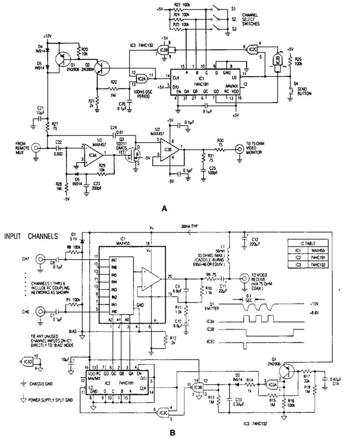
In the video system shown in Figs. A and R, a single coaxial cable transmits power to a remote location, selects one of eight video channels, and returns the chosen signal. This system can select from multiple remote surveillance...

This is a simple portable audio amplifier circuit. The circuit is built around the TEA2025 integrated circuit, which is a monolithic audio amplifier housed in a 16-pin dual in-line package manufactured by UTC. The circuit features an internal thermal...

Using four batteries, similar to those found in a flashlight, it is possible to produce hydrogen and oxygen at a rate equivalent to approximately 42 liters of regular-grade fuel per hour. While the batteries remain functional, they can generate...
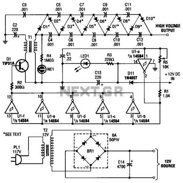
In the miniature high-voltage DC generator, the circuit receives input from a 12 V DC power supply, which is amplified to produce a 10,000 V DC output. This process induces a pulsating signal of opposite polarity in the secondary...
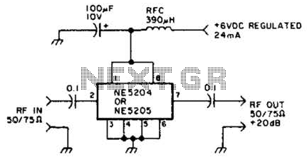
The Signetics NE5204 or NE5205 can be utilized in this audio frequency to 350-MHz (-30 dB) preamplifier. For a requirement of 600 MHz at 3 dB, the NE5205 should be employed. The noise figure is 4.8 dB at 75...

This straightforward design of an inverter circuit is capable of delivering high output power with an efficiency of approximately 75%. It provides guidance on constructing an inverter that can meet most power requirements at a reasonable cost. The article...