
555 constitute an ultrasonic transmitter circuit diagram

The ultrasonic transmitter circuit utilizes a 555 timer IC configured in astable mode to produce a continuous square wave output at 40kHz. This frequency is suitable for ultrasonic applications, such as distance measurement or pest deterrence. The 555 timer is powered by a 9V DC supply, which is connected to the VCC pin of the IC. The ground pin is connected to the circuit ground.
The frequency of oscillation is determined by external resistors and a capacitor connected to the 555 timer. Typically, two resistors (R1 and R2) and a capacitor (C1) are selected to set the desired frequency. The values of these components can be calculated using the formula:
\[ f = \frac{1.44}{(R1 + 2R2) \cdot C1} \]
For a frequency of 40kHz, appropriate values for R1, R2, and C1 must be chosen, ensuring that they are within the operational limits of the 555 timer.
The output from the 555 timer is connected to a T-40-16 ultrasonic transducer, which converts the electrical signal into ultrasonic sound waves. The transducer is specifically designed to operate efficiently at 40kHz, providing optimal performance for the intended application.
The circuit's operating current of 40 to 45mA indicates a low power consumption, making it suitable for battery-operated devices. The control distance of more than 8 meters suggests that the emitted ultrasonic signals can effectively travel this distance, allowing for various applications in sensing and communication.
To ensure stability and reliability, decoupling capacitors may be added near the power supply pins of the 555 timer and the transducer. This helps to filter out any noise from the power supply, improving the performance of the circuit. Additionally, a heat sink may be considered for the transducer if it operates at higher power levels for extended periods.
Overall, this ultrasonic transmitter circuit is a versatile and efficient design suitable for various applications requiring ultrasonic signal transmission.3 feet from the oscillating pulse output 555 of 40kHz drive T-40-16 work, so that emit ultrasonic signals of 40kHz. Circuit voltage of 9V, operating current 40 ~ 45mA, control distance is more than 8m. alt=" Ultrasonic transmitter circuit 555 constituted"> 555 constituting the ultrasonic wave transmitting circuit
Related Circuits
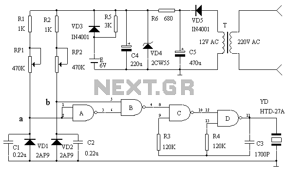
This circuit serves as an over-temperature alarm and cooling system utilizing CD4011 four NAND gate integrated circuits to monitor the oven's temperature. In the event of a thermostat circuit failure or power outage, if the internal temperature exceeds or...
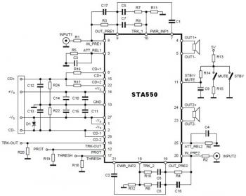
This is a stereo amplifier circuit diagram. The amplifier will produce stereo output channels with a power audio output that can reach up to 70W for each channel. The amplifier is built using the STA550 chip from STMicroelectronics. It...
This circuit blanks the CRT starting just before retrace begins. Since the CRT sits at a -1200 volt potential, the blanking circuit must also be based at -1200 volts. Note the capacitors, C40, C41, and C43 which allow the...
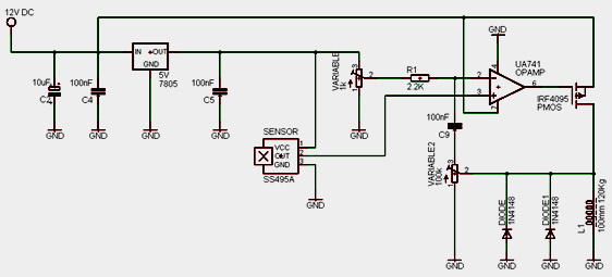
A laser trip wire that activates a camera. An ambient light sensor from Vishay, the TEMT6000, operates as an NPN transistor connected to a 555 timer in bistable mode. The output is directed to a logic inverter for quick...
Instructions for supervising landscaping projects recommended by satellite relay protection and automatic safety devices. This includes information on the general table for three remote programs related to petrochemical engineering construction, electrical transmission, and the intelligent implementation of community weak...
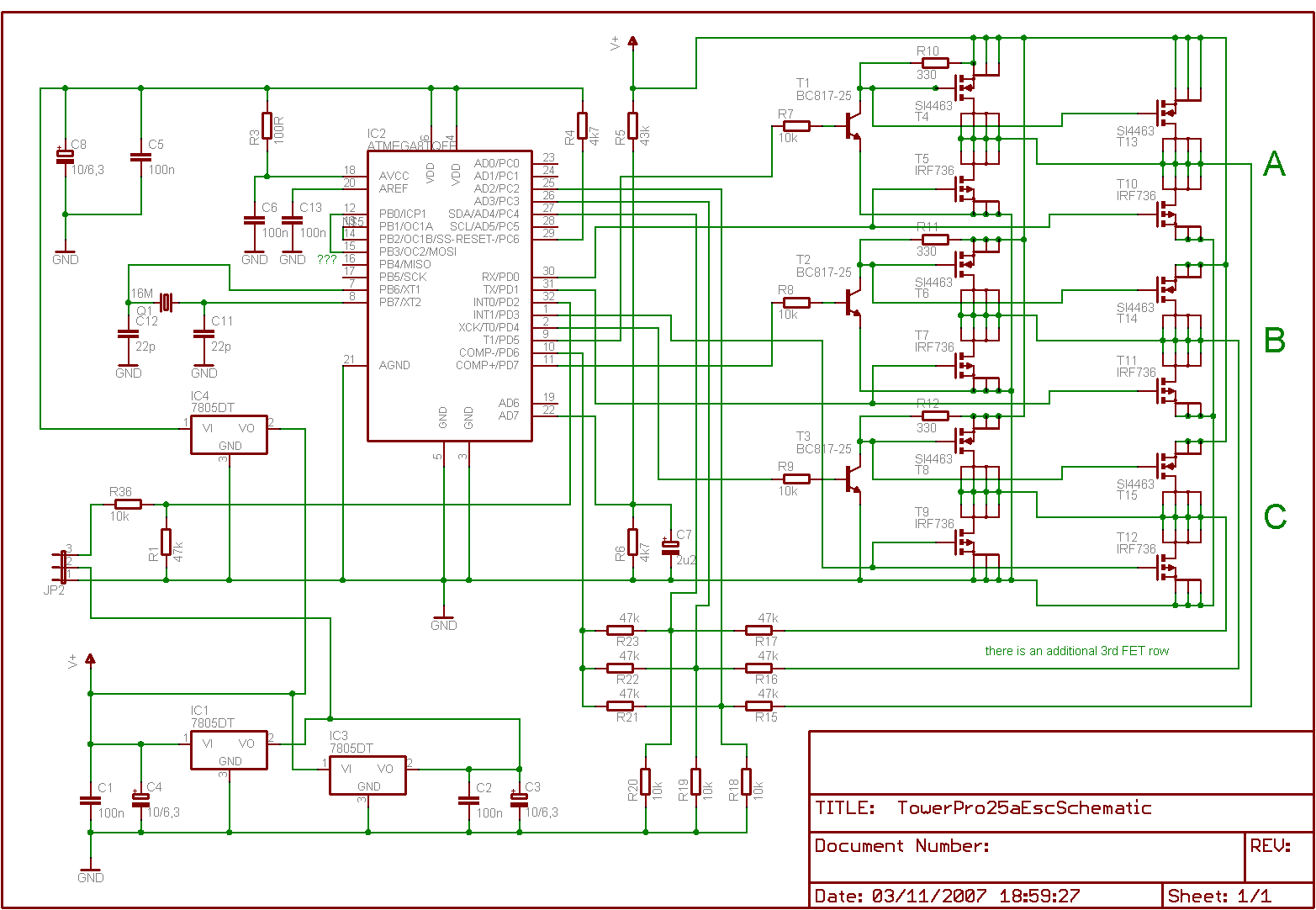
Is it feasible to eliminate the Electronic Speed Controllers (ESCs) from a multicopter configuration and substitute them with a single circuit board to control all the motors? The current setup consists of eight motors, each requiring an individual ESC,...