
circuit board for throttle control

The proposal to consolidate the control of multiple motors in a multicopter setup into a single circuit board presents several engineering challenges and opportunities. A single circuit board design would ideally integrate the functionalities of multiple ESCs into one unit, thereby reducing weight, minimizing potential points of failure, and potentially lowering costs.
The circuit board would require a microcontroller capable of managing the throttle signals for all motors simultaneously. This microcontroller should be programmed to interpret the input from the flight controller, which typically provides commands based on pilot input or autonomous flight algorithms. Each motor would still need to be driven by a power stage capable of handling the current and voltage requirements, which could be achieved through high-efficiency MOSFETs arranged in a bridge configuration.
Additionally, the circuit board would need to incorporate robust thermal management solutions to dissipate heat generated during operation, as multiple motors will demand significant power. Implementing current sensing for each motor could enhance performance monitoring and provide feedback to the flight controller, allowing for real-time adjustments to ensure optimal performance and safety.
Safety features should also be considered in the design, such as overcurrent protection, thermal shutdown, and fail-safe mechanisms to ensure that the multicopter can land safely in the event of a malfunction.
In summary, while the integration of ESC functions into a single circuit board for a multicopter is technically feasible and could yield numerous benefits, it requires careful consideration of power management, thermal dissipation, and safety protocols to ensure reliable operation.Would it be possible to remove the ESCS from a multicopter setup and replace them with a 1 single circuit board to throttle all the engines? I have a 8 motor setup wich is 8 ESCS wich is 8times the way and 8 times the possibility of failure or broken down ESCS.
For the price those ESCS costs coudent we design a circuit board that manages to throttle the motors from any setup by itselfs? I believe draganfly company is using this they have a very small circuit board that controls the motors.
🔗 External reference
Related Circuits
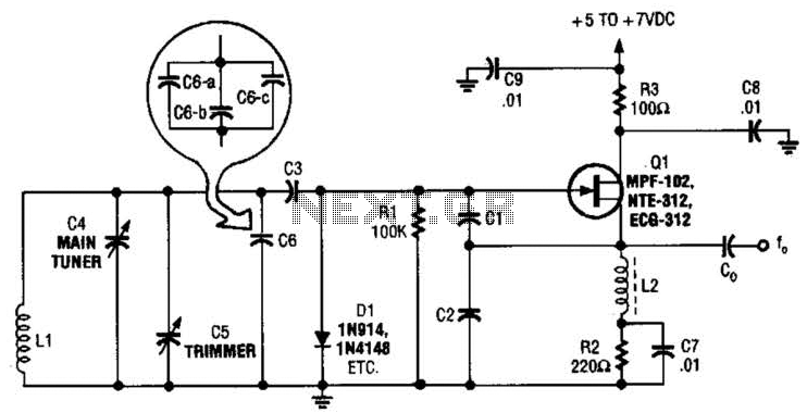
This basic VFO (Voltage Controlled Oscillator) operates within the 3 to 6 MHz frequency range and is commonly utilized in amateur radio applications, employing a Colpitts oscillator configuration. For operation at frequencies between 5 to 5.5 MHz, capacitors C2...
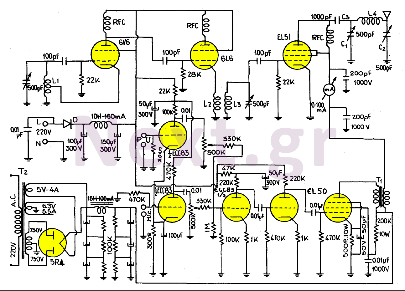
This transmitter, equipped with a quality antenna and utilized under optimal conditions, can achieve a range exceeding 45 km. The configuration benefits from the output lamp's elevation, enhancing the fidelity of the transmitted signal. The 6V6 lamp is employed...
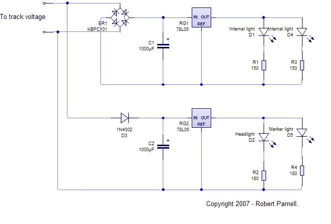
An LED, or Light Emitting Diode, is a semiconductor device that allows current to flow in one direction while blocking it in the opposite direction. This characteristic makes LEDs polarized components, having a positive side known as the anode...
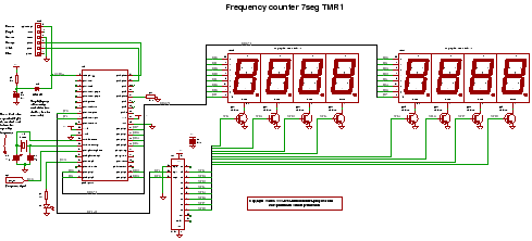
C code for a frequency counter circuit operating up to approximately 50 MHz, utilizing a multiplexed seven-segment display and employing Timer 1 to count the edges of the input signal. The frequency counter circuit described operates effectively within the range...
This Project is used to control a single phase Motor from any where in the world through the telephone. The circuit consists of a DTMF tone detector and a powerful 8 bit Microcontroller AT89S52. The Microcontroller senses the DTMF...
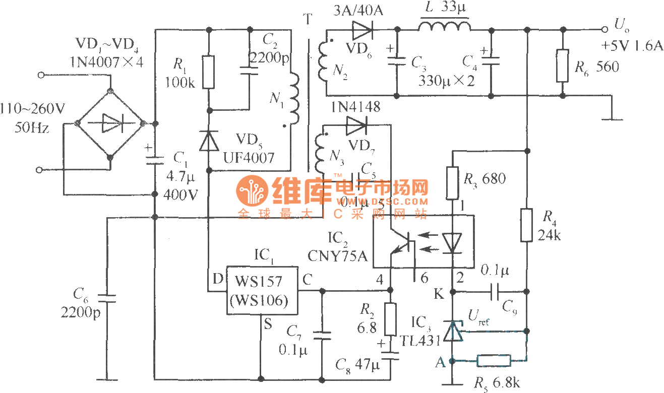
The +5V, 1.6A precision switching power supply circuit is depicted in the figure. This circuit utilizes a photoelectric coupler (CNY75A) and an adjustable precision parallel regulator (TIA31). R3 serves as the current limiting resistor, while R4 and R5 function...